Vaporizing and heating system

A heating system and vaporization chamber technology, applied in lighting and heating equipment, heat exchanger types, indirect heat exchangers, etc. Good effect, high thermal efficiency and reasonable structure design

Inactive Publication Date: 2018-03-06
史婷琪
View PDF0 Cites 0 Cited by
  • Summary
  • Abstract
  • Description
  • Claims
  • Application Information

AI Technical Summary

Problems solved by technology

[0002] The traditional method of flushing wells and wax removal uses fuel oil as the combustion medium, which takes a long time to warm up, consumes a lot of energy, costs a lot, and produces black smoke during combustion, which pollutes the environment. Therefore, it needs to be vaporized and then burned, but the engine water cannot provide enough heat for vaporization. , but it is still manual operation during operation, over temperature, over pressure, oil shortage, water shortage and other states in the operation process all rely on manual observation and judgment, and there are defects such as high labor intensity and potential safety hazards

Method used


Image

  • Vaporizing and heating system

Examples


Embodiment 1

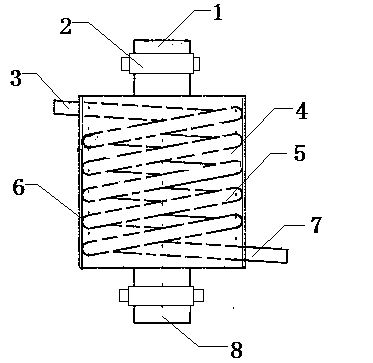
[0013] This embodiment provides a vaporization heating system, which is characterized in that: the vaporization heating system includes a liquefied gas inlet (1), a flange (2), an engine water inlet (3), a vaporization chamber (4), a heating Coil pipe (5), insulation layer (6), engine water outlet (7), liquefied gas outlet (8);

[0014] Among them: the liquid water in the engine flows through the engine water inlet (3), the heating coil (5), and the engine water outlet (7) in order to form circulating liquid water, and the liquefied gas flows through the liquefied gas inlet (1), vaporized chamber (4), liquefied gas outlet (8).

[0015] Both the liquefied gas inlet (1) and the liquefied gas outlet (8) are provided with flanges (2) for connection and installation.

[0016] The inside of the vaporization chamber (4) is provided with multiple vacuum insulation layers (6).


PUM


Abstract

A vaporization heating system, characterized in that: the vaporization heating system includes a liquefied gas inlet, a flange, an engine water inlet, a vaporization chamber, a heating coil, an insulation layer, an engine water outlet, and a liquefied gas outlet; wherein: the engine The liquid water in the tank flows through the engine water inlet, heating coil, and engine water outlet in sequence to form circulating liquid water, and the liquefied gas flows through the liquefied gas inlet, vaporization chamber, and liquefied gas outlet in sequence, and multi-layer vacuum insulation layers are set inside the vaporization chamber , Both the liquefied gas inlet and the liquefied gas outlet are equipped with flange connection installations. Advantages of the present invention: the vaporization heating system described in the present invention has reasonable structural design, simple principle, good vaporization effect, can make full use of material resources, does not need to add any chemical reagents, is energy-saving and environmentally friendly, does not pollute the environment, and has small heat loss. High thermal efficiency and other advantages.

Description

technical field [0001] The invention relates to an energy-saving and environment-friendly well flushing and wax removal technology, and in particular provides a vaporization heating system. Background technique [0002] The traditional method of flushing wells and wax removal uses fuel oil as the combustion medium, which takes a long time to warm up, consumes a lot of energy, costs a lot, and produces black smoke during combustion, which pollutes the environment. Therefore, it needs to be vaporized and then burned, but the engine water cannot provide enough heat for vaporization. , but it is still operated manually during the operation, and the over-temperature, over-pressure, oil shortage, water shortage and other states in the operation process all rely on manual observation and judgment, and there are defects such as high labor intensity and potential safety hazards. Contents of the invention [0003] The object of the present invention is to solve the technical problem...

Claims


Application Information

Patent Timeline
Patent Type & Authority Applications(China)
IPC IPC(8): F28D7/02
CPCF28D7/024
Inventor 史婷琪
Owner 史婷琪
Why Eureka
Try Eureka