A high pressure washer

A technology of a high-pressure cleaner and a high-pressure plunger pump, which is applied to cleaning methods and appliances, cleaning methods using liquids, chemical instruments and methods, etc., and can solve the impact on the life of the spray gun connecting pipe, bursting of the connecting pipe and the spray gun, and operator injury and other problems to achieve the effect of improving service life, reducing pumping pressure and reducing damage

Active Publication Date: 2019-12-13
南京汇涛节能科技有限公司
View PDF9 Cites 0 Cited by
  • Summary
  • Abstract
  • Description
  • Claims
  • Application Information

AI Technical Summary

Problems solved by technology

[0003] The Chinese patent application number 201520638978.0 discloses a high-pressure cleaning machine, which is provided with a bracket, a motor, a high-pressure pump, and a spray gun. The motor drives the high-pressure pump to supply water to the spray gun, so that high-pressure water can be sprayed at high pressure and high flow rate from the spray gun, thereby achieving Cleaning effect; but when people need to close the valve for a short time during the spraying process, the valve on the spray gun will be closed, but when the valve is directly closed, the high-pressure, high-flow rate water generated by the high-pressure pump will directly act on the spray gun instantly, so that the spray gun and the connection The water pressure in the pipe rises instantly, and the high-pressure pump stops after detecting that the internal pressure is too high, which affects the life of the spray gun and the connecting pipe. When the instantaneous impact pressure is too large, the connecting pipe and the spray gun are prone to burst, resulting in harm to the operator

Method used


Image

  • A high pressure washer
  • A high pressure washer
  • A high pressure washer

Examples


Embodiment 1

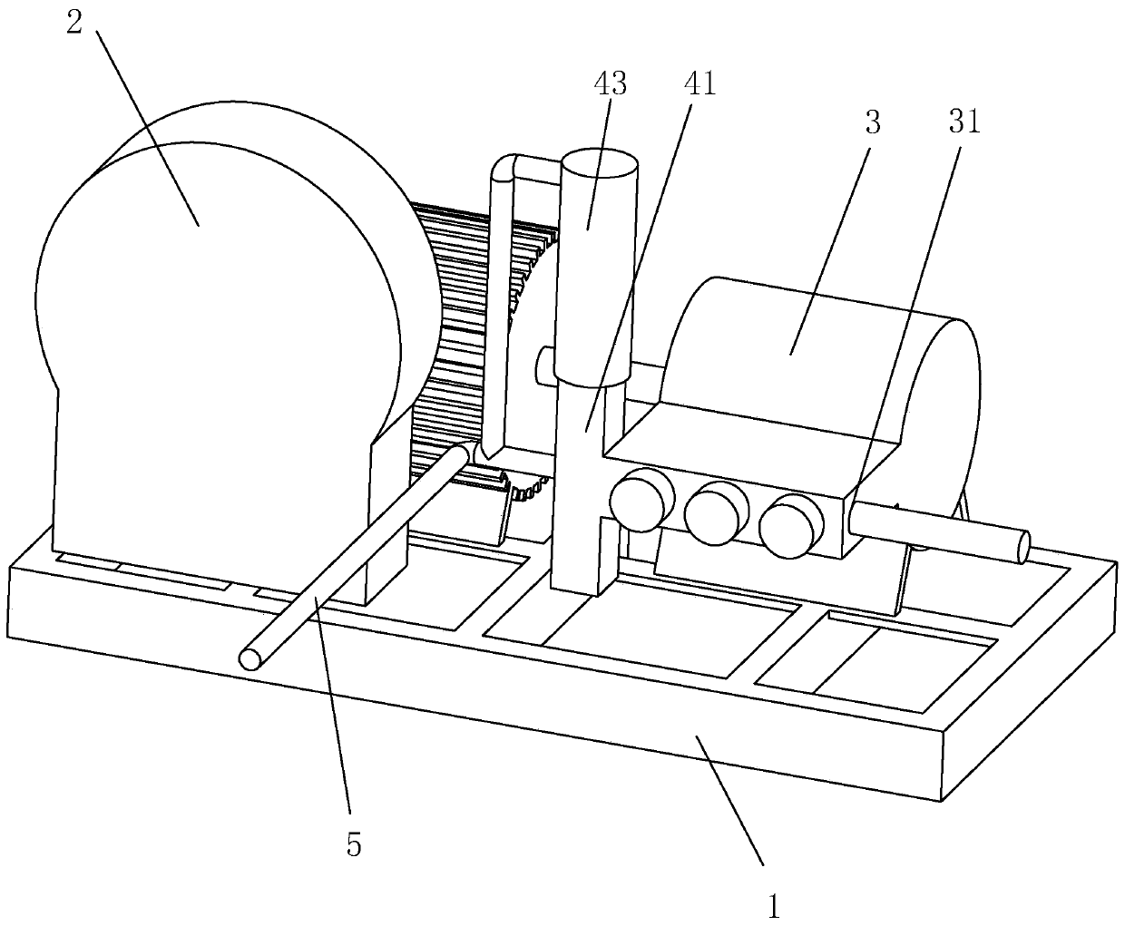
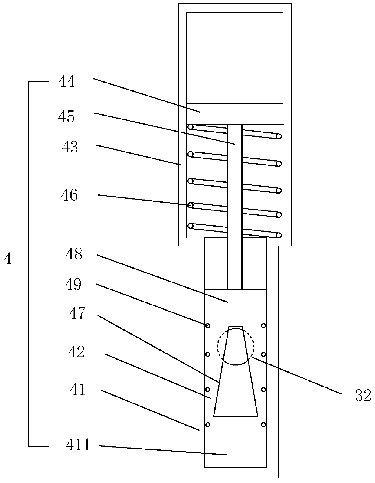
[0038] Example 1: A high-pressure cleaner, such as figure 1 , 2 As shown, including the base 1, the control box 2, the high-pressure plunger pump 3, the nozzle, the control box 2, the high-pressure plunger pump 3 are all fixedly connected to the base 1 by bolts, and the control box 2 controls the high-pressure plunger pump 3 The opening and closing of the high-pressure plunger pump 3 can be directly detected through the control box 2 to automatically adjust the pressure of the high-pressure plunger pump 3. The nozzle end is connected to the high-pressure plunger pump through the connecting pipe 5 3 connection, people operate the switch on the nozzle to spray water, and people can operate the nozzle to flush and clean the device. The high-pressure plunger pump 3 is provided with a water inlet 31 and a water outlet 32, and the water enters the high pressure through the water inlet 31 The plunger pump 3 presses water into the connecting pipe 5 through the water outlet 32 ​​through ...

Embodiment 2

[0043] Embodiment 2: A high-pressure cleaner, which differs from embodiment 1 in that Figure 5 As shown, the base 1 is provided with a centrifugal pump 6 and a water storage tank 7, the centrifugal pump 6 is connected to the water storage tank 7, the water inlet 31 is connected to the water storage tank 7, and the top of the water storage tank 7 is provided with an exhaust valve 71.

[0044] The centrifugal pump 6 pumps external water into the water storage tank 7 for storage and filtration, so that the high-pressure plunger pump 3 can directly pump water from the water storage tank 7, so as to prevent external debris from affecting the normal operation of the high-pressure plunger pump 3 Work, and the delivery force generated by the high-pressure plunger pump 3 is all acting on pressing water into the connecting pipe 5, thereby effectively improving the water-pressing effect of the high-pressure plunger pump 3. When the centrifugal pump 6 pumps the water to the water storage tan...

Embodiment 3

[0046] Embodiment 3: A high-pressure cleaner, the difference from embodiment 2 is that Figure 7 , 8 As shown, the base 1 is provided with a fixed ring 81, the fixed ring 81 is fixedly connected with a supporting foot 82, the supporting foot 82 is fixedly connected to the base 1, and the inner circumferential side of the fixed ring 81 is in contact with the outer circumferential side of the water storage tank 7. A cushion rubber pad 83 is also provided on the inner circumferential side of the fixing ring 81.

[0047] Since the water storage tank 7 basically plays an intermediate role and will filter debris, etc., the water storage tank 7 needs to be disassembled and cleaned frequently. Therefore, the water storage pipe is separated from the high-pressure plunger pump 3 and the centrifugal pump 6 It can be pulled out vertically from the fixing ring 81, and after cleaning, it can be fixed by inserting it into the fixing ring 81, thereby facilitating the disassembly and installation ...


PUM


Abstract

The invention discloses a high-pressure washer which has the advantage of avoiding too high instantaneous water pressure so as not cause damage when a spray pipe is closed. According to the technicalscheme, a water inlet and a water outlet are formed in a high-pressure plunger pump, and a valve device is arranged on the high-pressure plunger pump. The valve device comprises a valve body and a flow limiting valve plate, and the valve body is fixedly connected with one end, close to the water outlet, of the high-pressure plunger pump. A valve chamber is formed in the valve body, and the two ends of the valve chamber are respectively connected with a connecting pipe and the water outlet. The flow limiting valve plate is arranged in the valve chamber. A cushioning cylinder body is arranged onthe valve body, and a sealed piston is arranged in the cushioning cylinder body. A connecting rod connected with the flow limiting valve plate is arranged at one end, close to the valve chamber, of the sealed piston, and the other end of the cushioning cylinder body communicates with the connecting pipe. An elastic reset piece for enabling the sealed piston to move to one end far away from the valve body is arranged on the cushioning cylinder body. A flow limiting hole is formed in the flow limiting valve plate, and the section of the flow limiting hole is trapezoidal. The two ends of the trapezoidal flow limiting hole are respectively a large bottom surface and a small bottom surface, and the small bottom surface end of the flow limiting hole is close to the cushioning cylinder body.

Description

Technical field [0001] The invention relates to the field of cleaning machinery, in particular to a high-pressure cleaning machine. Background technique [0002] The high-pressure cleaner uses a motor to drive a high-pressure plunger pump to pump water, and then through the high-pressure plunger pump to deliver the water to the nozzle for high-pressure and high-velocity spraying, so that the sprayed water can be used to flush other equipment. The cleaning principle is: the impact of water is greater than the adhesion of dirt to the surface of the object, and the high-pressure water will peel off the dirt and wash it away to reach a cleaning device that cleans the surface of the object, because it uses high-pressure water to clean the dirt, unless it is very stubborn It is necessary to add a little detergent to the oil stains, otherwise the foam produced by the strong water pressure is enough to take away the general dirt. Because the high pressure water column is used to clean th...

Claims


Application Information

Patent Timeline
Patent Type & Authority Patents(China)
IPC IPC(8): B08B3/02B08B13/00
CPCB08B3/02B08B13/00
Inventor 吴道峰
Owner 南京汇涛节能科技有限公司
Why Eureka
Try Eureka