
Device for reducing pressure of photovoltaic module in rain and snow weather

A photovoltaic module and weather technology, applied in photovoltaic power generation, electrical components, semiconductor devices, etc., can solve the problems of reducing the pressure of photovoltaic modules and damage of photovoltaic modules, and achieve the effect of avoiding pressure shock and impact damage

Inactive Publication Date: 2018-02-27
成都亿伏科技有限公司
View PDF5 Cites 1 Cited by
  • Summary
  • Abstract
  • Description
  • Claims
  • Application Information

AI Technical Summary

Problems solved by technology

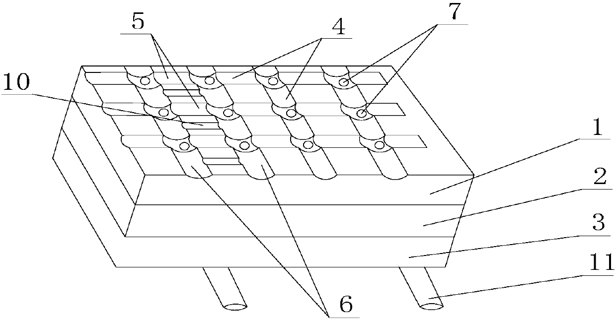
[0004] The invention solves the problem that photovoltaic modules in the prior art are damaged due to the impact of rainwater due to excessive rain in rainy weather, and provides equipment for reducing the pressure of photovoltaic modules in rainy and snowy weather, which can be used in rainwater The weather effectively guides the rainwater falling on the photovoltaic modules, reduces the pressure on the photovoltaic modules in rainy weather, and avoids the damage of the photovoltaic modules caused by the excessive impact of rainwater

Method used


Image

  • Device for reducing pressure of photovoltaic module in rain and snow weather
  • Device for reducing pressure of photovoltaic module in rain and snow weather
  • Device for reducing pressure of photovoltaic module in rain and snow weather

Examples


Embodiment 1

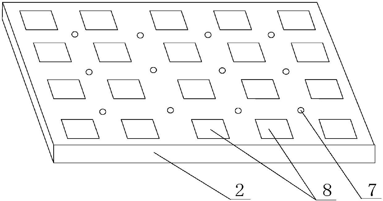
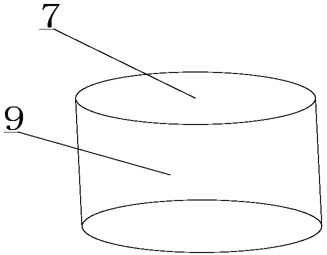
[0022] Such as Figure 1-3 As shown, the equipment for reducing the pressure of photovoltaic modules in rainy and snowy weather includes a glass plate 1, a solar cell panel 2, and a back plate 3. The solar cell panel 2 is arranged between the back plate 3 and the glass plate 1, and the glass plate 1 is located directly above the solar panel 2, the back plate 3 is located directly below the solar panel 2, and the side of the glass plate 1 away from the solar panel 2 is provided with a drainage groove 4, and the drainage groove 4 includes a horizontal Drainage groove 5, vertical drainage groove 6, described horizontal drainage groove 5 is arranged in parallel to each other on the side of glass plate 1 away from solar panel 2, and described vertical drainage groove 6 is arranged in parallel to each other on glass plate 1 away from solar energy One side of the battery board 2 is perpendicular to the horizontal drainage groove 5, and also includes a drainage groove 10, which is arr...

Embodiment 2

[0025] On the basis of Embodiment 1, the side of the back plate 3 away from the solar cell panel 2 is provided with a drainage channel 11, the drainage channel 11 is connected to the drainage hole 7, and the drainage channel 11 guides and drains the rainwater discharged in the drainage hole 7, The rainwater is discharged to a safe place through the drainage channel 11, so as to prevent the water discharged in the drainage hole 7 from affecting surrounding equipment or structures.


PUM


Abstract

The invention discloses a device for reducing the pressure of photovoltaic modules in rain and snow weather. The device comprises a glass plate, a solar cell panel and a back plate, wherein the solarcell panel is arranged between the back plate and the glass plate which is located over the solar cell panel, and the back plate is located under the solar cell panel; drainage grooves are formed in the side, away from the solar cell panel, of the glass plate, the drainage grooves include the horizontal drainage grooves and the vertical drainage grooves, the horizontal drainage grooves are formedin the side, away from the solar cell panel, of the glass plate in a mutually parallel mode, and the vertical drainage grooves are formed in the side, away from the solar cell panel, of the glass plate in a mutually parallel mode and are perpendicular to the horizontal drainage grooves; drain holes are formed in the intersection positions of the horizontal drainage grooves and the vertical drainage grooves, the drain holes run through the glass plate, the solar cell panel and the back plate, and the drain holes are formed in the gaps between batteries in the solar cell panel. Rainwater flows into the drain holes through the horizontal drainage grooves and the vertical drainage grooves and flows out, so that the huge shock damage of the rainwater on the photovoltaic modules is avoided.

Description

technical field [0001] The invention relates to photovoltaic components, in particular to equipment for reducing the pressure of photovoltaic components in rainy and snowy weather. Background technique [0002] Photovoltaic modules (commonly known as solar panels) are composed of solar cells or solar cells of different specifications cut by a laser cutting machine or a steel wire cutting machine. Since the current and voltage of a single solar cell are very small, then we first connect them in series to obtain a high voltage, and then connect them in parallel to obtain a high current, and then output it through a diode (to prevent current return). And package them on a stainless steel, aluminum or other non-metal frame, install the upper backplane on the top and the lower backplane on the back, fill with nitrogen, and seal. The whole is called a module, that is, a photovoltaic module or a solar cell module. [0003] In the prior art, there is a problem that the photovoltai...

Claims


Application Information

Patent Timeline
Patent Type & Authority Applications(China)
IPC IPC(8): H01L31/18
CPCH01L31/1876Y02E10/50Y02P70/50
Inventor 张博丛伟伦黄帅
Owner 成都亿伏科技有限公司
Learn More