
Distillation apparatus

一种蒸馏装置、蒸馏塔的技术,应用在蒸馏分离、共沸蒸馏、分馏等方向,能够解决设备运行成本和设备成本增加等问题,达到延长寿命、降低运行成本、降低设备成本的效果

Active Publication Date: 2018-02-23
LG CHEM LTD
View PDF7 Cites 2 Cited by
  • Summary
  • Abstract
  • Description
  • Claims
  • Application Information

AI Technical Summary

Problems solved by technology

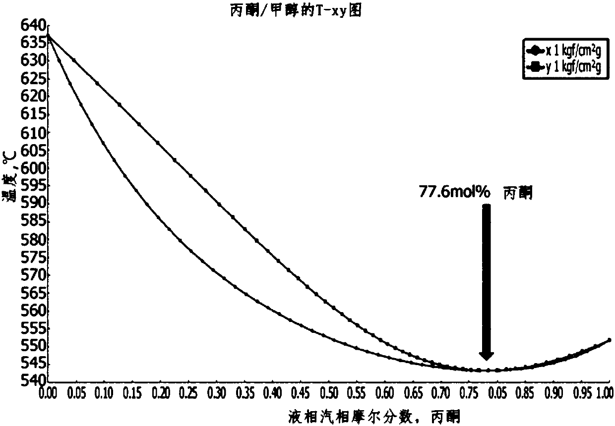
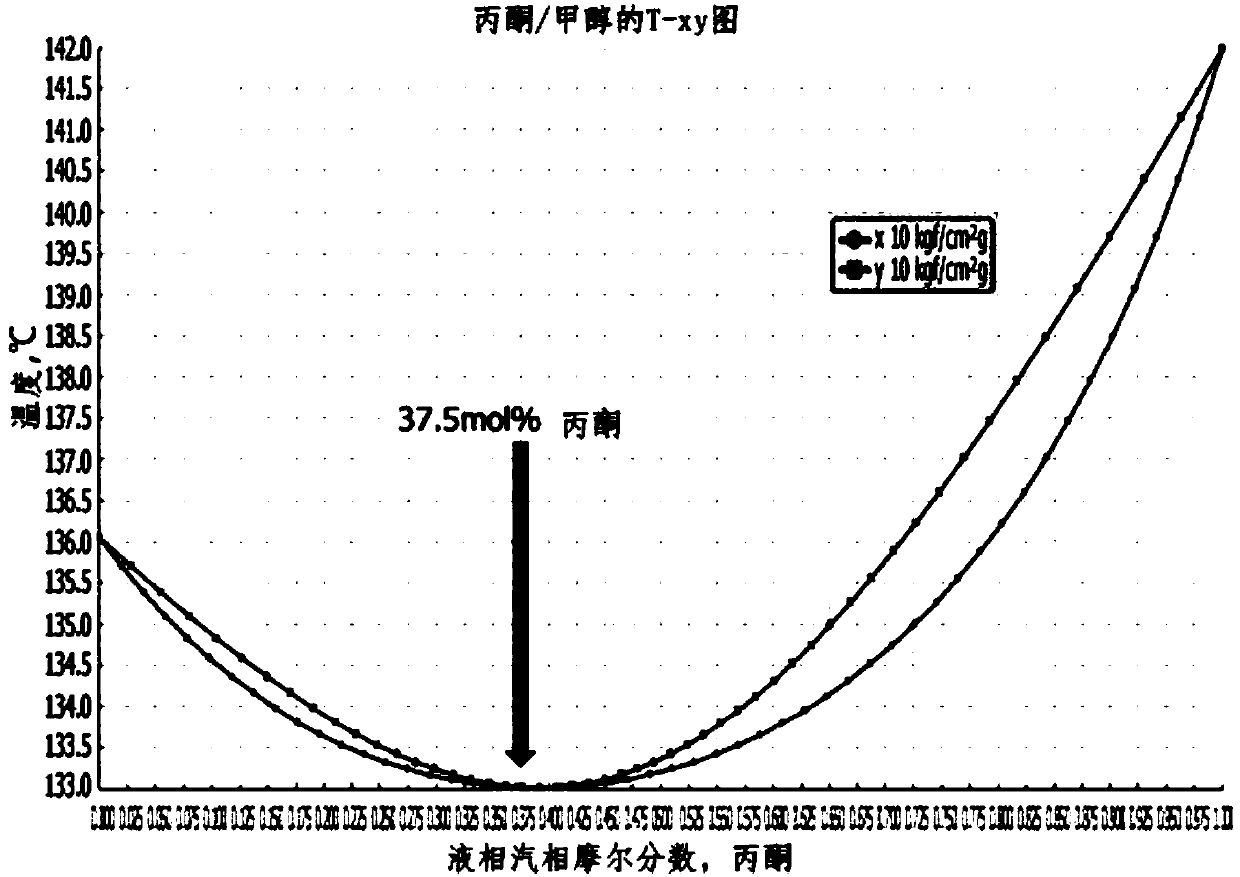
However, since the mixture of acetone and methanol forms an azeotrope, and at 1kgf / cm 2 g and 10kgf / cm 2 The boiling points at each pressure of g are opposite, so at least two or more separation and purification towers are required to separate them, and therefore there is a problem that the operating cost of the equipment and the equipment cost are greatly increased

Method used


Image

  • Distillation apparatus
  • Distillation apparatus
  • Distillation apparatus

Examples


example 1

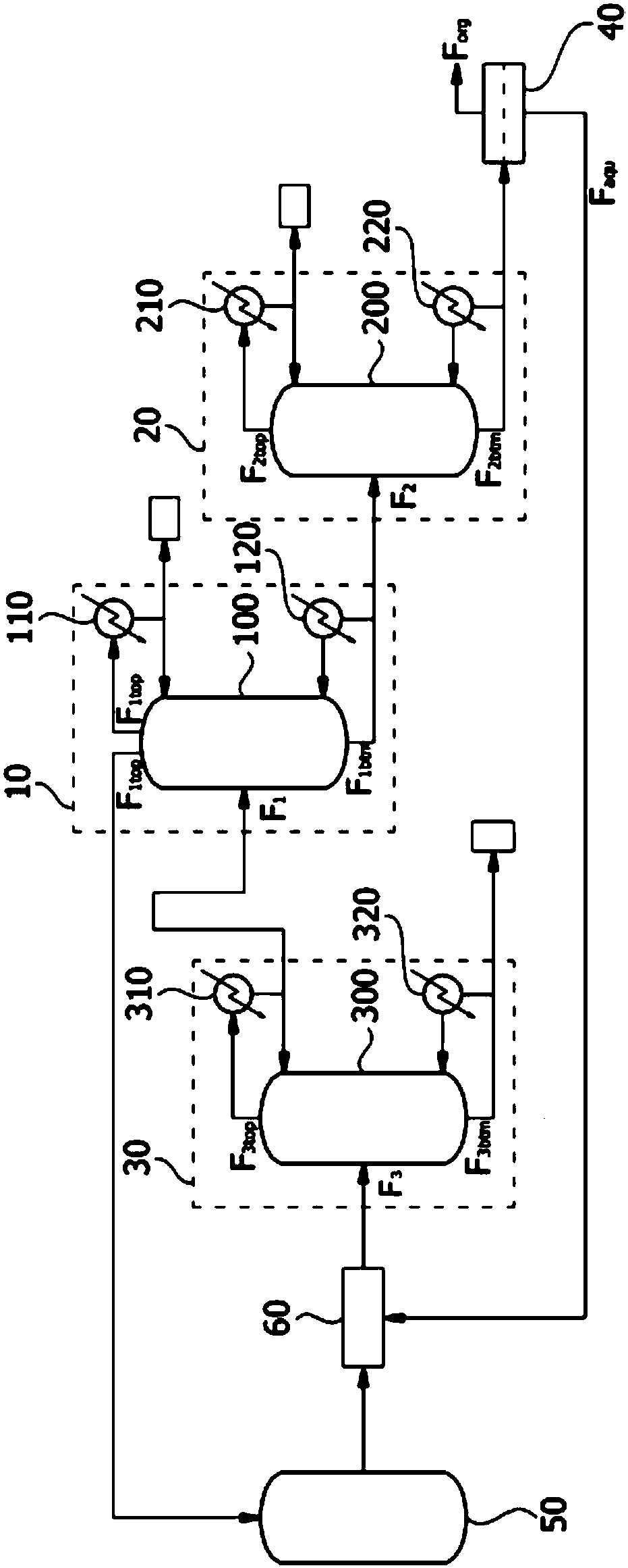
[0134] use Figure 8 The distillation unit separates acetone and methanol.

[0135] Specifically, a feedstock containing 55% by weight of acetone, 22% by weight of cumene, 4% by weight of α-methylstyrene, 0.03% by weight of methanol and 0.14% by weight of high-boiling components was heated at 88°C The temperature and the flow rate of 43,000kg / hr were introduced into the first distillation column with 65 theoretical stages.

[0136] The first top stream withdrawn from the top region of the first distillation column is passed through the first condenser and partly refluxed into the top region of the first distillation column. The remainder of the first overhead stream is separated and stored as a product comprising 99.8% by weight of acetone and 0.02% by weight of methanol, and the first bottom stream withdrawn from the bottom region of the first distillation column passes through a first reboiler, and A portion is refluxed to the bottom region of the first distillation column...

example 2

[0143] Acetone and methanol were separated by the same method as in Example 1 except that the operating conditions of the second distillation column were changed as shown in Table 1 below.

[0144] In the case of separating acetone and methanol using the distillation apparatus of Example 2, the amount of energy used in the first reboiler and the second reboiler and the removal rate of methanol are shown in Table 1 below.

example 3

[0146] use Figure 9 The distillation unit separates acetone and methanol.

[0147] Specifically, a feedstock containing 55% by weight of acetone, 22% by weight of cumene, 4% by weight of α-methylstyrene, 0.03% by weight of methanol and 0.14% by weight of high-boiling components was heated at 88°C The temperature and the flow rate of 43,000kg / hr were introduced into the first distillation column with 65 theoretical stages.

[0148] The first top stream withdrawn from the top region of the first distillation column is passed through the first condenser and partly refluxed into the top region of the first distillation column. The remainder of the first overhead stream is separated and stored as a product comprising 99.8% by weight of acetone and 0.02% by weight of methanol, and the first bottom stream withdrawn from the bottom region of the first distillation column passes through a first reboiler, and A portion is refluxed to the bottom region of the first distillation column...


PUM


Abstract

The present application relates to a distillation apparatus. According to the distillation apparatus of the present application, since a methanol removal distillation column is positioned at a location allowing the separation of methanol to be relatively easy when separating a material containing acetone and methanol by using the distillation apparatus, a problem caused by the accumulation of methanol in a process can be solved and the lifespan of a catalyst can be extended by lowering the amount of methanol in an acetone product. Further, methanol can be removed with excellent efficiency fromthe lower stream of a distillation column from which a final acetone product is obtained, only by means of a conventional phase separator and the one methanol removal distillation column, which is additionally provided, and thus an acetone product to be obtained from the upper part of the distillation column from which the final acetone product is obtained can be obtained in a high purity, and operation costs and equipment installation costs can be greatly saved.

Description

technical field [0001] The present application relates to a distillation apparatus. [0002] This application claims the benefit of priority over Korean Patent Application No. 10-2015-0094491 filed on July 2, 2015, the entire disclosure of which is incorporated herein by reference. Background technique [0003] Phenol is used in various fields as a raw material for various synthetic resins (including phenolic resins) such as polycarbonate resins and epoxy resins, or as a raw material in the pharmaceutical industry, as well as detergents such as nonylphenol or various color Raw materials for coatings. [0004] The production of phenol from cumene is well known. For example, cumene is oxidized with an oxygen-containing gas to form cumene hydroperoxide, which is then decomposed over an acidic catalyst to produce phenol and acetone. [0005] In the above-mentioned process of generating phenol, various side reactions occur simultaneously. For example, a trace amount of methan...

Claims


Application Information

Patent Timeline
Patent Type & Authority Applications(China)
IPC IPC(8): C07C37/74B01D3/32C07C39/04
CPCB01D3/141B01D3/143B01D3/36C07C37/08C07C45/53C07C45/84C07C39/04C07C49/08B01D3/32
Inventor 秋渊旭李成圭金台雨朴钟瑞申俊浩
Owner LG CHEM LTD
Learn More