
Circuit capable of enhancing drive capability

A technology to enhance drive and capability, applied in the direction of adjusting electrical variables, control/regulating systems, instruments, etc., can solve the problems of insufficient drive capability and large internal resistance, and achieve the effect of enhancing drive capability and increasing drive current.

Inactive Publication Date: 2018-02-23
MINGFENG POWER ELECTRONICS IND CO LTD
View PDF4 Cites 0 Cited by
  • Summary
  • Abstract
  • Description
  • Claims
  • Application Information

AI Technical Summary

Problems solved by technology

When the MOS transistor Q1 uses a larger specification, the internal resistance is very large, and the driving capability of U1 will be insufficient at this time

Method used


Image

  • Circuit capable of enhancing drive capability
  • Circuit capable of enhancing drive capability

Examples


Embodiment Construction

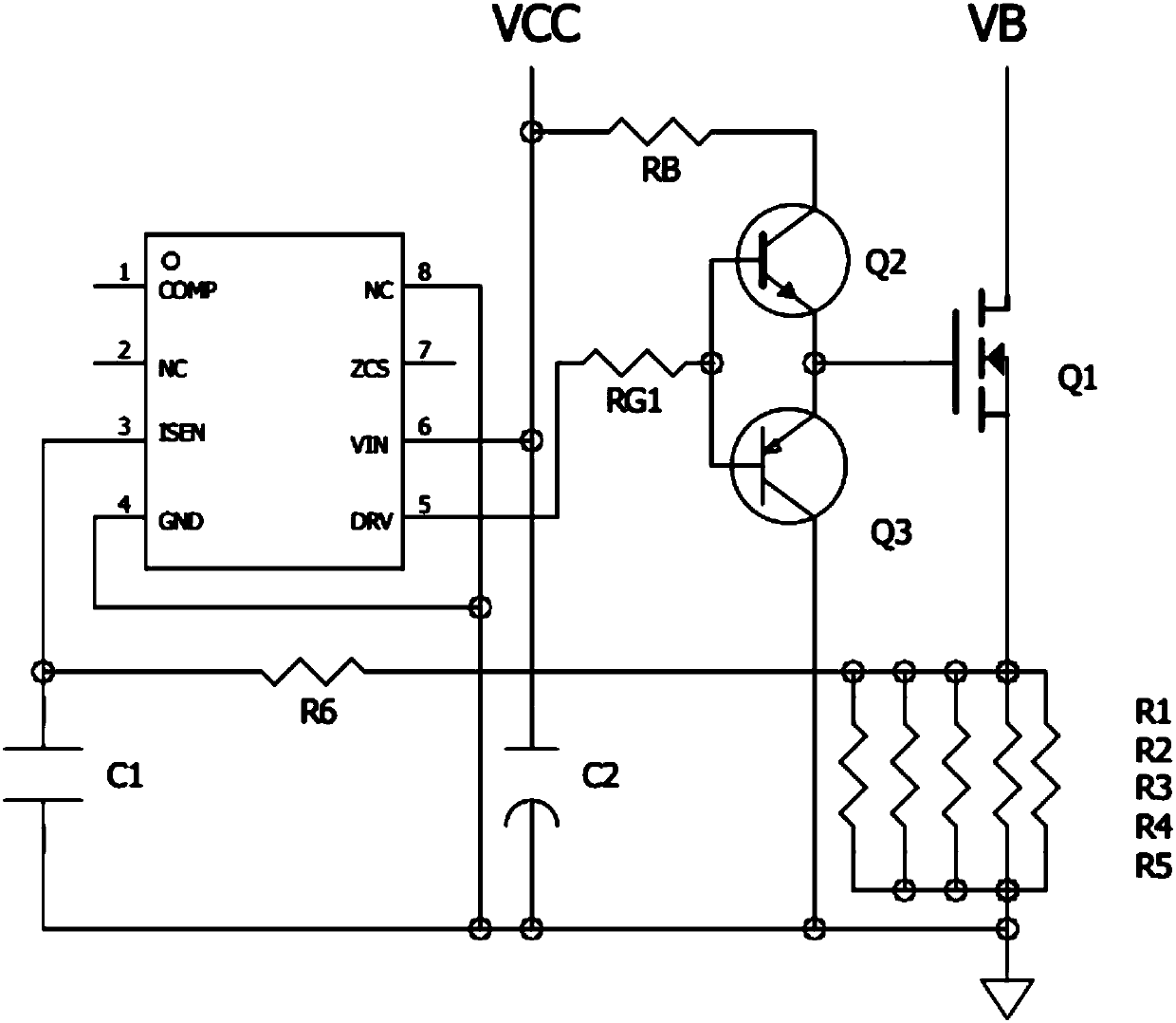
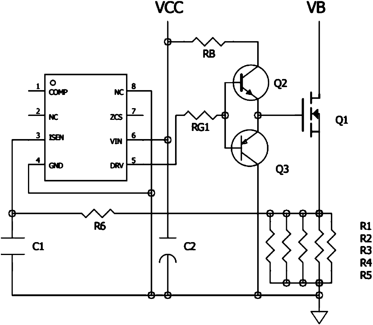
[0013] The present invention proposes a circuit with enhanced driving capability, such as figure 2 shown, including the first resistor R B , the second resistor R G1 , a first transistor Q2, a second transistor Q3, a MOS transistor Q1, a third resistor R1, a fourth resistor R2, a fifth resistor R3, a sixth resistor R4 and a seventh resistor R5.

[0014] The first resistor R B One end of the first resistor R is connected to the input voltage VCC and the power input terminal VIN of the driver chip U1, and the first resistor R B The other end of the second transistor Q2 is connected to the collector of the first transistor Q2, the emitter of the first transistor Q2 is connected to the emitter of the second transistor Q3 and the gate of the MOS transistor Q1, the collector of the second transistor Q3 is grounded, and the The base of the first transistor Q2 and the base of the second transistor Q3 are connected to the second resistor R G1 One end of the second resistor R G1 T...


PUM


Abstract

The invention relates to a circuit capable of enhancing drive capability. The circuit comprises a first resistor, a second resistor, a first transistor, a second transistor, a MOS tube, a third resistor, a fourth resistor, a fifth resistor, a sixth resistor and a seventh resistor. The circuit overcomes the defect that an existing drive circuit is low in drive capability; in the circuit structure,drive current is increased, and the drive purpose is achieved; the circuit structure can be applied to circuits with the need for enhancing drive capability.

Description

technical field [0001] The invention relates to a driving circuit, in particular to a circuit with enhanced driving capability. Background technique [0002] The drive circuit is located between the main circuit and the control circuit, and is used to amplify the signal of the control circuit (that is, to amplify the signal of the control circuit so that it can drive the power transistor), which is called the drive circuit. [0003] Existing drive circuits such as figure 1 As shown, the driving signal of the driver chip U1 is output from the fifth pin DRV, and directly drives the MOS transistor Q1 through RG. When the MOS tube Q1 uses a larger specification, the internal resistance is very large, and the driving capability of U1 will be insufficient at this time. Contents of the invention [0004] In view of this, it is necessary to provide a circuit for enhancing the driving capability to solve the problem. [0005] A circuit for enhancing driving capability, comprisin...

Claims


Application Information

Patent Timeline
Patent Type & Authority Applications(China)
IPC IPC(8): G05F1/56
CPCG05F1/561
Inventor 曾映明李军
Owner MINGFENG POWER ELECTRONICS IND CO LTD
Learn More