
Pneumatic driving system of gas turbine

A gas turbine, pneumatic drive technology, applied in gas turbine installations, machines/engines, mechanical equipment, etc., can solve the problems of increasing lubricating oil demand and storage, generator overload, difficult to seal, etc., to achieve small temperature rise, high starting The effect of torque and emission without pollution

Pending Publication Date: 2018-02-23
大连欧谱纳透平动力科技有限公司
View PDF0 Cites 0 Cited by
  • Summary
  • Abstract
  • Description
  • Claims
  • Application Information

AI Technical Summary

Problems solved by technology

The motor drive method requires a large motor, and the connection between the output end of the motor and the gas turbine is also limited by the space. When the driven end fails, the generator will be overloaded; and for the hydraulic drive method, It is necessary to provide a high-pressure oil source, which is not easy to seal, and increases the demand and storage of lubricating oil, and the system is more complicated

Method used


Image

  • Pneumatic driving system of gas turbine
  • Pneumatic driving system of gas turbine
  • Pneumatic driving system of gas turbine

Examples


Embodiment Construction

[0013] The gas turbine aerodynamic drive system involved in the invention will be described in detail below with reference to the accompanying drawings.

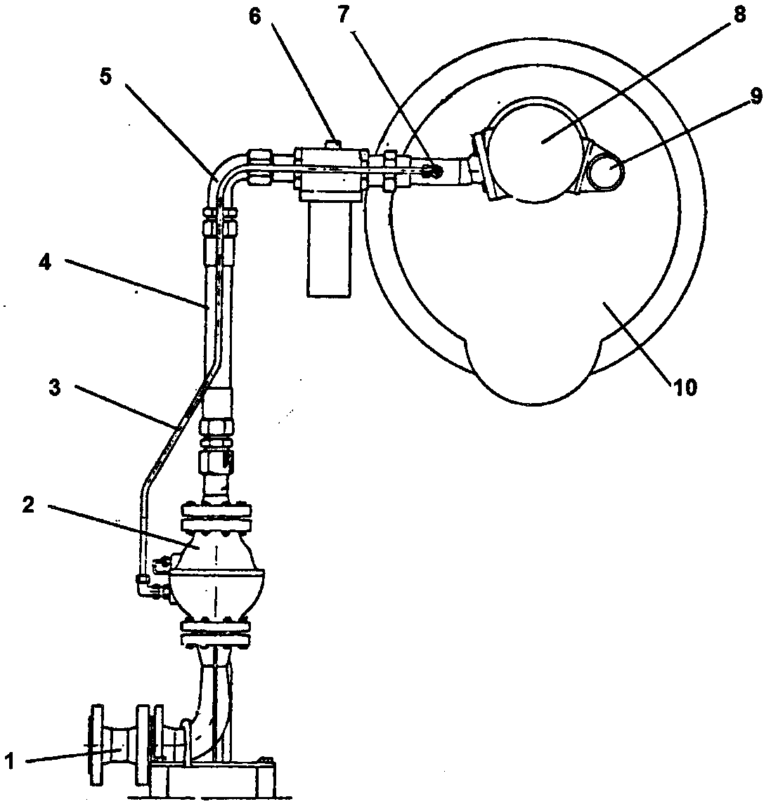
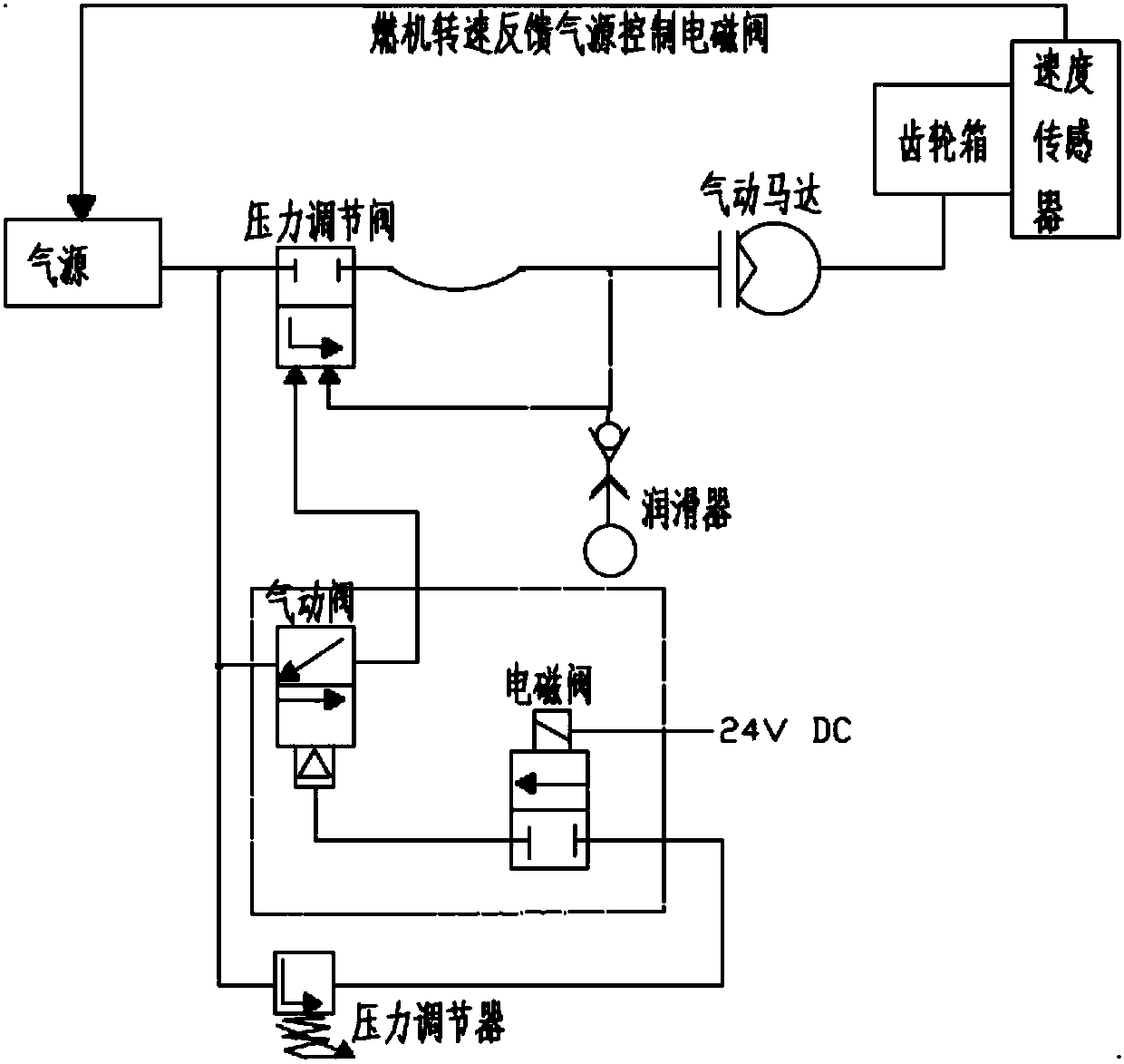
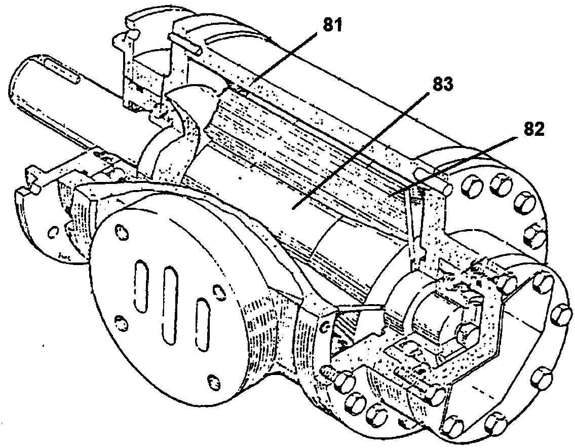
[0014] Such as figure 1 and 2 As shown, the air source is connected to the air source flange 1 on the pipe and bracket assembly to provide the working medium for the entire system. A flexible pipe 4 and an elbow 5 are optionally connected between the pressure regulating valve 2 and the lubricator assembly 6 on the pipe and bracket assembly. The end of the pipe and bracket assembly is connected to the air motor 8, and the output shaft of the air motor 8 is connected to the gearbox 10 of the gas turbine.

[0015] In order to facilitate installation and reduce the influence of steam turbine vibration on the gas source device, a section of flexible pipeline 4 can be arranged in the pipeline and bracket assembly.

[0016] In order to accurately adjust the outlet pressure, a pressure-taking pipe interface 7 is provided at the e...


PUM


Abstract

The invention discloses a pneumatic driving system of a gas turbine. The pneumatic driving system comprises an air source, a pipeline and bracket assembly, and a pneumatic motor. The air source is connected with an air source flange in the pipeline and bracket assembly, thus, a work medium is provided for the system, the air source flange is connected to a pressure adjusting valve to adjust the pressure of an output end, then connected to a lubricator through a flexible pipeline so that a little of oil gas can be added into the work medium to provide lubrication for the pneumatic motor, and finally connected to the pneumatic motor, and an output shaft of the pneumatic motor is connected to a gear box of the gas turbine. The pneumatic driving system of the gas turbine is simple in overall structure, capable of generating no spark during working, being applied to explosive radiative high-temperature dusty occasions and environments with quite moist air, and free of electric leakage risk.Air serves as the medium of the system and is easy to get, and pollution-free emission is achieved.

Description

technical field [0001] The invention belongs to the technical field of gas turbines, and in particular relates to a gas turbine aerodynamic driving system. technical background [0002] The starting process of a gas turbine requires an external driving force. At present, most of them use electric motor drive, hydraulic drive and other driving methods. The motor drive method requires a large motor, and the connection between the motor output end and the gas turbine will also be limited by the space. When the driven end fails, the generator will be overloaded; and for the hydraulic drive method, It is necessary to provide a high-pressure oil source, which is not easy to seal, and increases the demand and storage of lubricating oil, and the system is more complicated. Contents of the invention [0003] The technical problem to be solved by the present invention is to provide a gas turbine aerodynamic drive system that utilizes the aerodynamic system to provide driving force...

Claims


Application Information

Patent Timeline
Patent Type & Authority Applications(China)
IPC IPC(8): F02C7/27F01C1/344F01C19/08
CPCF01C1/3447F01C19/08F02C7/27
Inventor 毛玉升赵治平刘思广冯群
Owner 大连欧谱纳透平动力科技有限公司
Learn More