Cast-in-situ skeleton, preparation method and structural wall prepared from skeleton

A cast-in-place and skeleton technology, applied to walls, building components, building structures, etc., can solve the problems of increased construction procedures, complicated materials, affecting thermal insulation effect and service life, etc.

Inactive Publication Date: 2018-02-23
李天昊
View PDF0 Cites 0 Cited by
  • Summary
  • Abstract
  • Description
  • Claims
  • Application Information

AI Technical Summary

Problems solved by technology

[0002] At present, the construction of cast-in-place frames and construction projects in our country adopts the formwork system to support cast-in-place. The above-mentioned pouring method has the following defects: First, there are many materials and accessories, such as all-steel formwork, steel-wood formwork, and multi-layer wood formwork. mold, plastic film, aluminum alloy mold, etc., and accessories include pull bolts, etc., before the construction period, according to the actual situation of the project, the materials used are complicated, the quantity is huge, the material consumption is large, the capital investment is large, and the cost is high; second, the construction process is complicated , the construction process increases, resulting in a large investment in human resources, high labor intensity, slow construction period, and high labor costs
Because concrete leakage is difficult to be effectively maintained in the natural environment, the strength of concrete is difficult to guarantee, and it is labor-intensive; third, most of the traditional external wall insulation is connected to the wall by sticking nails, and the surface is 3-6mm Thick mortar protective layer. Practice has proved that due to the influence of wind, sun, rain and other natural environments, the thermal insulation layer and protective layer in this technology generally crack and fall off in a short period of time, which affects the thermal insulation effect. and the service life, the insulation layer is mostly made of polystyrene board, which is a flammable material. During the construction period, the exposed time is long, the protective layer is thin, and it is easy to be damaged and leaked for a long time. It is easy to cause a fire when it encounters an open flame; The composite insulation board combined with the mesh and the insulation board is mostly used. The insulation board and the mesh are connected by a horizontal wire drawing welded to the mesh, and the insulation board and the mesh are connected by a horizontal wire drawing welded to the mesh. The above composite The thermal insulation board has the following defects: 1. The wall, the thermal insulation board and the mesh are connected by horizontal wire drawing. There are many steel wires penetrating the thermal insulation board, and the heat conduction area is large. In winter, the energy in the house is lost, which wastes energy. The indoor temperature is lowered, which wastes air conditioning energy; 2. Manual welding is mostly used, which requires a lot of labor, wastes a lot, and the processing technology is complicated. First, weld the mesh, then weld the horizontal wire drawing on the mesh, and then connect the insulation board; 3. There are many solder points, It is easy to desolder and open welding; 4. The mesh is easy to be exposed during construction, and the corrosion resistance is poor; 5. Due to the poor flatness of the mesh, ordinary concrete and vibrating rods cannot be used for vibration, and self-compacting concrete can only be used, which not only costs a lot 6. The insulation board is prone to displacement during the pouring process, causing leakage of the insulation package and affecting the quality of the project

Method used


Image

  • Cast-in-situ skeleton, preparation method and structural wall prepared from skeleton
  • Cast-in-situ skeleton, preparation method and structural wall prepared from skeleton
  • Cast-in-situ skeleton, preparation method and structural wall prepared from skeleton

Examples


Embodiment Construction

[0085] The structure and application principle of the cast-in-place framework, the preparation method of the cast-in-place framework and the structural wall prepared by using the cast-in-place framework of the present invention will be further described in detail below in conjunction with the accompanying drawings and specific embodiments.

[0086] In order to express more clearly, the inner side and the outer side expressed in the text are relative to the entire cast-in-place framework, that is, the side of the cast-in-place framework with the first membrane shell is defined as the outer side, and the side with the second membrane shell is defined as the outer side. Side is defined as medial.

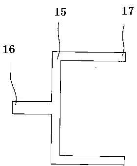
[0087] Such as figure 1 , figure 2 and image 3 As shown, the cast-in-place framework of the present invention includes the first membrane shell 1 located on the outermost side, and the inner surface of the first membrane shell 1 is provided with a keel 2 containing at least two paral...


PUM


Abstract

The invention belongs to the technical field of a cast-in-place frame, a preparation method thereof and a building made of the frame, and discloses a cast-in-place frame, a preparation method and a structural wall made of the frame. Its main technical features are: it includes the first membrane shell located on the outermost side, on the inner surface of the first membrane shell, a keel with at least two parallel pasting planes is pasted, and the second pasting plane on the inner side of the keel is connected with the insulation board Bonding the outer side of the outer side of the keel, an outer tie rod is arranged on the first membrane shell between adjacent keels, an inner tie rod is arranged inside the outer tie rod, and a second bonding member is arranged inside the inner tie rod , the second membrane shell is glued on the second adhesive member, and a tie rod connecting piece consisting of one outer connection end and two inner connection ends is arranged between the inner tie rod and the outer tie rod. After the support is completed, it can be poured directly. It is convenient to process and install, saves a lot of formwork, and greatly reduces the construction cost.

Description

technical field [0001] The invention belongs to the technical field of a cast-in-place frame, a preparation method thereof and a building made of the frame, and in particular relates to a cast-in-place frame, a preparation method and a structural wall made of the frame. Background technique [0002] At present, the construction of cast-in-place frames and construction projects in our country adopts the formwork system to support cast-in-place. The above-mentioned pouring method has the following defects: First, there are many materials and accessories, such as all-steel formwork, steel-wood formwork, and multi-layer wood formwork. mold, plastic film, aluminum alloy mold, etc., and accessories include pull bolts, etc., before the construction period, according to the actual situation of the project, the materials used are complicated, the quantity is huge, the material consumption is large, the capital investment is large, and the cost is high; second, the construction process...

Claims


Application Information

Patent Timeline
IPC IPC(8): E04B2/86
CPCE04B2/86E04B2/8635E04B2002/8688
Inventor 李天昊
Owner 李天昊
Why Eureka
Try Eureka