
Outdoor illuminating mosquito killer

A technology of outdoor lighting and mosquito killer, which is applied in the direction of lighting devices, lighting devices, lighting and heating equipment, etc., and can solve the problem of lamp body burning, high-voltage grid electrode wire of mosquito killer can not be cleaned well, and mosquito killer Unstable operation and other problems, to achieve stable operation, ensure environmental safety, and enhance the effect of insecticide

Pending Publication Date: 2018-02-23
北京国强博源科技发展有限公司
View PDF9 Cites 4 Cited by
  • Summary
  • Abstract
  • Description
  • Claims
  • Application Information

AI Technical Summary

Problems solved by technology

[0004] In view of the shortcomings of the prior art described above, the purpose of the present invention is to provide an outdoor lighting mosquito killer, which is used to solve the problem that the high-voltage grid electrode wire of the mosquito killer in the prior art cannot be cleaned well, causing the mosquito killer to The operation is unstable, and it may even cause the problem of burning the lamp body

Method used


Image

  • Outdoor illuminating mosquito killer
  • Outdoor illuminating mosquito killer
  • Outdoor illuminating mosquito killer

Examples


Embodiment 1

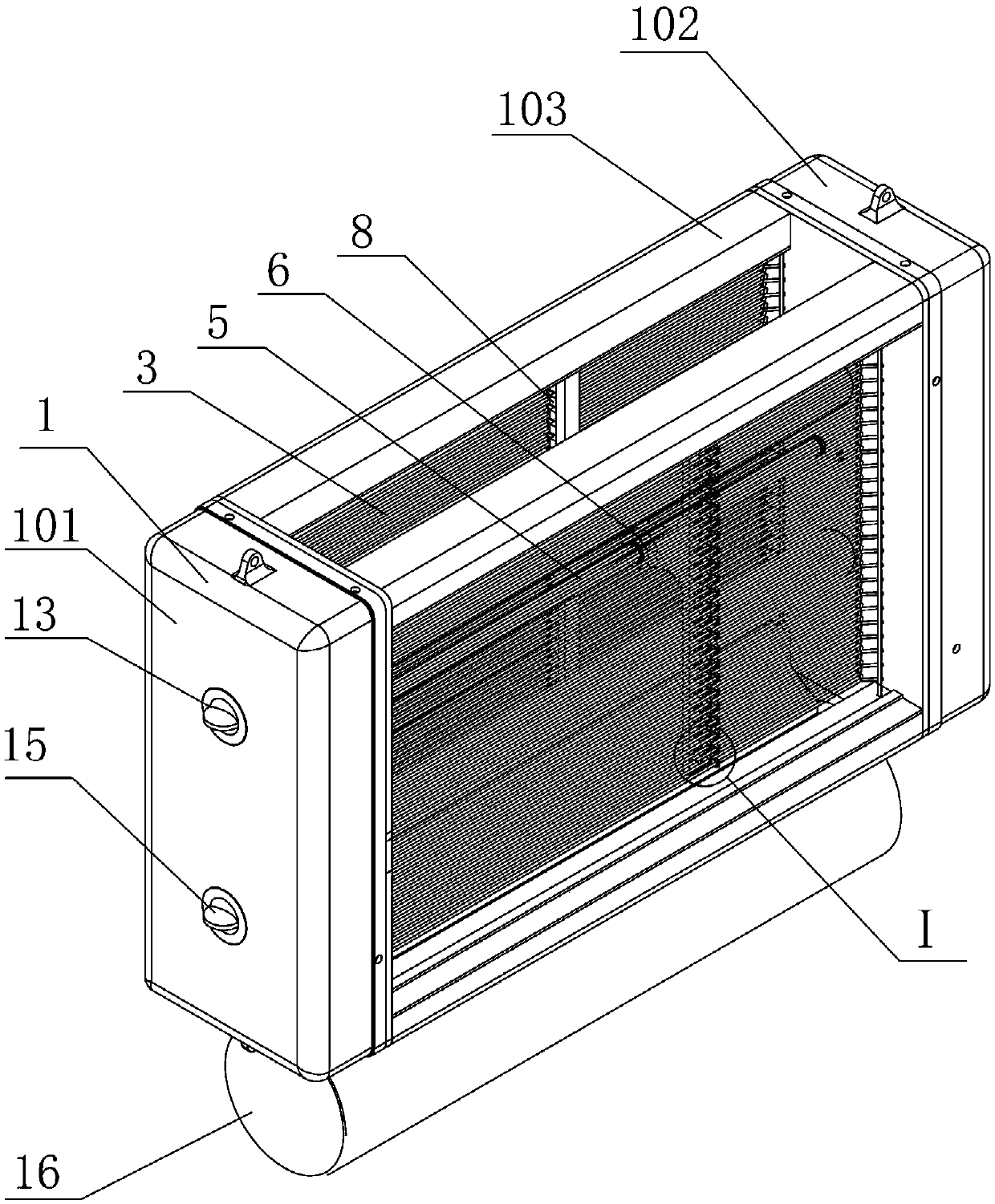
[0035] Example 1, such as Figure 1 to Figure 5 , the present invention provides an outdoor lighting mosquito killer, comprising: a housing 1, an insect-attracting light source, a high-voltage power grid 3, a cleaning mechanism, and an electrical control device; the insect-attracting light source is installed inside the housing 1, and the A light-transmitting window is arranged on the side, and the high-voltage power grid 3 is covered and installed on the light-transmitting window; the cleaning mechanism includes a drive motor 4, a lead screw 5, a lead screw nut 6, a cleaning frame 7 and a cleaning brush head 8 made of insulating material One end of the cleaning brush head 8 is fixedly mounted on the cleaning frame body 7, and the other end is in contact with the high-voltage power grid 3. The lead screw nut 6 is screwed on the lead screw 5 and is fixedly connected with the cleaning frame body 7. The end is rotatably installed on the housing 1, and the rotating main shaft of t...

Embodiment 2

[0044] Example 2, such as Image 6 The difference between this embodiment and Embodiment 1 is that a plurality of bent ceramic heads 901 are correspondingly hooked on a plurality of hard metal wires 301 .

[0045] In the present invention, the cleaning brush head is made of insulating material, which may be several ceramic heads in the above-mentioned embodiments, may also be a hair brush, or may be other insulating materials.

[0046] The working process of the cleaning mechanism of the present invention is as follows: the cleaning frame is located at the set initial position close to the first end box, when the high-voltage power grid needs to be cleaned, the cleaning mechanism control module controls the driving motor to rotate forward, and the driving motor drives the lead screw to rotate, and The nut screwed by the lead screw moves in a straight line, so that the cleaning frame and the cleaning brush head move along the screw to the direction of the second end box. When t...


PUM


Abstract

The invention discloses an outdoor illuminating mosquito killer which comprises a shell, insect trapping light sources, a high-voltage power grid, a cleaning mechanism and an electric control device.The insect trapping light sources are mounted inside the shell, a light transmission window is arranged on a side surface of the shell, and the high-voltage power grid is mounted on the light transmission window in a covering manner; the cleaning mechanism comprises a driving motor, a lead screw, a lead screw nut, a cleaning frame and cleaning brushes, the cleaning brushes are made of insulating materials, two ends of the lead screw are rotatably mounted on the shell, a rotary spindle of the driving motor is fixedly connected with an end of the lead screw, the lea screw nut is screwed on the lead screw and is fixedly connected with the cleaning frame, an end of each cleaning brush is fixedly arranged on the cleaning frame, a cleaning mechanism control module is arranged in the electric control device, and the driving motor can rotate clockwise and anticlockwise by the aid of the cleaning mechanism control module. The outdoor illuminating mosquito killer has the advantages that the high-voltage power grid can be thoroughly cleaned, accordingly, short circuit of the high-voltage power grid can be prevented, the insect killing capacity can be improved, and the service life of the outdoor illuminating mosquito killer can be prolonged.

Description

technical field [0001] The invention relates to the technical field of insect killers, in particular to an outdoor lighting mosquito killer. Background technique [0002] With the improvement of people's awareness of environmental protection and health, people pay more and more attention to physical insecticide. Replacing chemical insecticide with physical insecticide is the future development direction. Light trapping and killing insects is an important technical means of physical integrated pest control. In recent years, chemical pesticides have been used in the planting process. Although the yield and appearance quality of plants have been improved, they will cause serious damage to environmental elements such as soil and water systems. In the obtained plants, excessive chemical residues will directly affect people's health. Today, with the continuous improvement of material conditions, people not only meet the demand for food, but also pay more attention to food safety ...

Claims


Application Information

Patent Timeline
Patent Type & Authority Applications(China)
IPC IPC(8): A01M1/04A01M1/22F21V33/00
CPCA01M1/04A01M1/223F21V33/00
Inventor 宋国强
Owner 北京国强博源科技发展有限公司
Learn More