
Heat pump system and method for operating it

A heat pump system, a technology in operation, applied in transportation and packaging, heating/cooling equipment, air handling equipment, etc., can solve problems such as complex wiring, expensive control devices, complexity, etc., and achieve small structural space, weight and cost reduction Effect

Active Publication Date: 2018-02-16
BAYERISCHE MOTOREN WERKE AG
View PDF13 Cites 16 Cited by
  • Summary
  • Abstract
  • Description
  • Claims
  • Application Information

AI Technical Summary

Problems solved by technology

[0003] The following problem usually arises in electric vehicles or hybrid vehicles: a continuous heat-generating internal combustion engine and a corresponding high-temperature cooling circuit are mostly absent and the heat required to heat the coolant for the purpose of heating the vehicle passenger compartment must be obtained from another one source acquisition
[0004] However, the different heat sources often have to be connected separately, resulting in complex wiring
To heat or cool the passenger compartment as required and simultaneously cool one or more power components, disadvantageously, complex wiring is required, often requiring the use of many lines and valves, especially expensive switching valves
In particular with regard to the air conditioning of the vehicle interior, different operating states often require corresponding settings in which the heat is to be introduced in each case differently into the vehicle interior and / or the environment, which in turn requires a large number of valves, especially complex valves. and expensive controls
This leads to high costs especially in electric vehicles, since here, as mentioned above, overall less heat is available and its efficient distribution is therefore all the more critical

Method used


Image

  • Heat pump system and method for operating it

Examples


Embodiment Construction

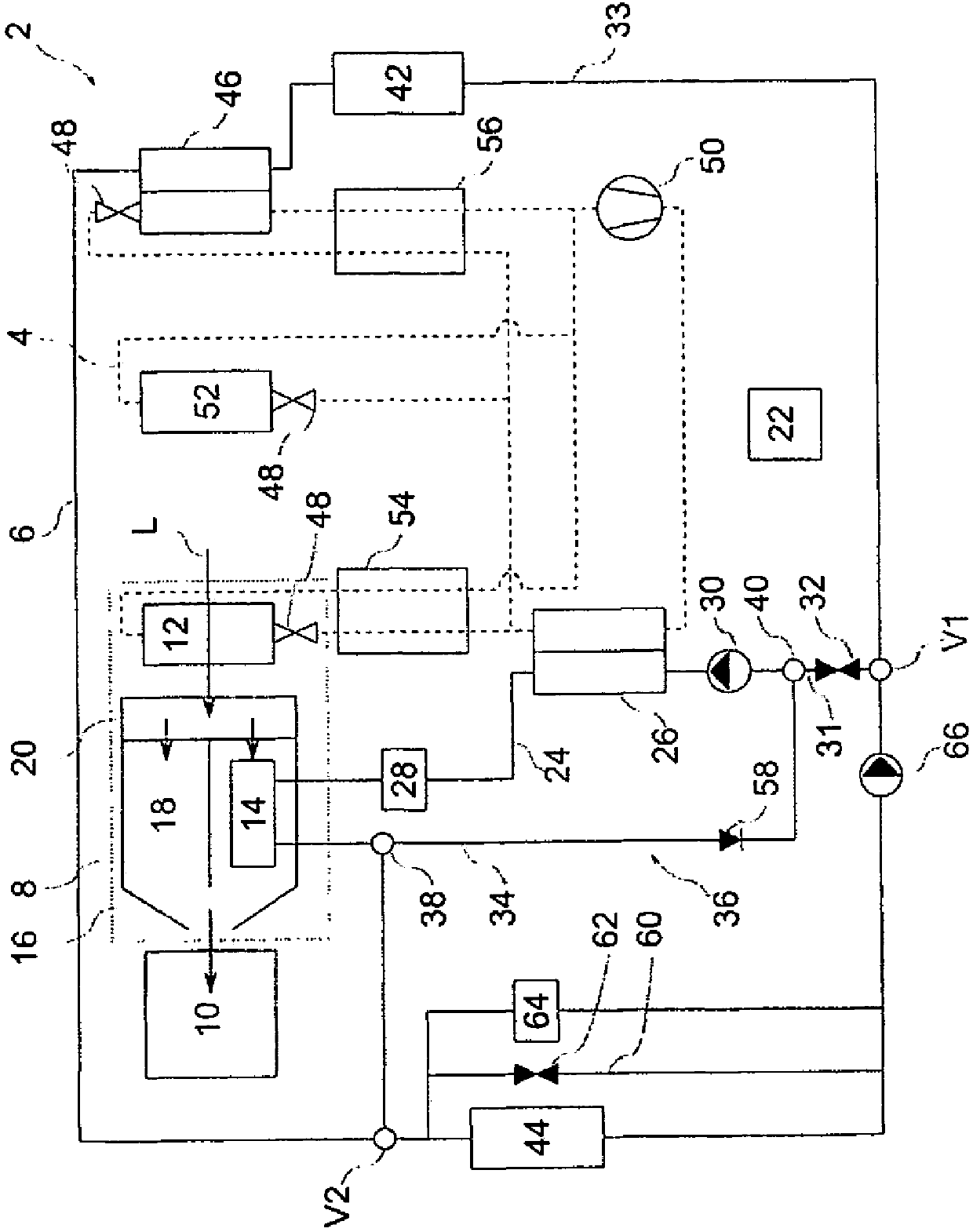
[0052] figure 1 Shown is a heat pump system 2 for a vehicle not shown in detail, in particular for an electric vehicle or a hybrid vehicle. The heat pump system 2 includes a refrigeration circuit 4 in which a refrigerant circulates, and a coolant circuit 6 in which a coolant, such as a water / glycol mixture, circulates. Refrigeration circuit 4 in figure 1 is indicated by a dashed line, and the coolant circuit 6 is indicated by a solid line. The coolant circuit 6 is a cooling circuit in which the coolant generally has a temperature between approximately -25°C to +70°C or even up to +90°C. The heat pump system 2 also includes an air conditioning device 8 for air conditioning the passenger compartment 10 , ie the interior of the compartment. To this end, the air conditioning device 8 has an air conditioning evaporator 12 connected to the refrigeration circuit 4 and a heating heat exchanger 14 connected to the coolant circuit 6 . The air conditioning evaporator 12 is used for c...


PUM


Abstract

The invention relates to a heat pump system (2) for air conditioning a vehicle, in particular an electric or hybrid vehicle, having an air conditioning unit (8) which has an air conditioning evaporator (12) and a heating heat exchanger (14), for air conditioning a passenger compartment (10) of the vehicle, having a condenser (26), for transmitting heat from a refrigeration circuit (4) into a coolant circuit (6), having a chiller (46), for transmitting heat from the coolant circuit (6) into the refrigeration circuit (4), wherein the coolant circuit (6) has two branches (24, 33) which are parallel to one another downstream of a low temperature cooler (44), namely a heating branch (24) which can be shut off and in which the condenser (26) and the heating heat exchanger (14) are arranged, anda cooling branch (33), in which the chiller (46) and a low temperature heat exchanger (42) for cooling a vehicle component are arranged. The heat pump system (2) is characterized in that the low temperature cooler (44), the condenser (26) and the heating heat exchanger (14) are connected in series with respect to one another. In addition, the heat pump system (2) has a plurality of operating modes. Particularly flexible, inexpensive, robust and, above all, efficient air conditioning is realised on the basis of the special connection. Furthermore, the invention relates to a method for operatingthe heat pump system (2).

Description

technical field [0001] The invention relates to a heat pump system for air-conditioning a vehicle, in particular an electric vehicle or a hybrid vehicle, comprising an air-conditioning unit for air-conditioning a passenger compartment with an air-conditioning evaporator and a heating heat exchanger, for air-conditioning a passenger compartment Heat transfer from the refrigeration circuit to the condenser in the coolant circuit, Chiller for transferring heat from the coolant circuit to the refrigeration circuit with downstream cryocooler (NT-Kühler) Two branches connected in parallel to one another, namely a blockable heating branch, in which the condenser and the heating heat exchanger are arranged, and a cooling branch, in which the refrigerator and at least one vehicle component are arranged. Background technique [0002] A corresponding heat pump system is described in the applicant's unpublished application DE 102014217960. [0003] The following problem usually arises ...

Claims


Application Information

Patent Timeline
Patent Type & Authority Applications(China)
IPC IPC(8): B60H1/00
CPCB60H1/00899B60H2001/00928B60H1/00385B60H1/32284B60H1/00907B60H1/22B60H1/3213B60H2001/2237B60H2001/3288B60H2001/3291
Inventor O·霍恩R·赫博尔茨海默
Owner BAYERISCHE MOTOREN WERKE AG
Learn More