
A light field consistency detection phantom, method, device and equipment

A detection method and consistency technology, applied in the field of data processing, can solve problems such as insufficient flexibility of optical field consistency detection, and achieve the effect of solving insufficient flexibility

Active Publication Date: 2020-04-10
NEUSOFT MEDICAL SYST CO LTD
View PDF5 Cites 0 Cited by
  • Summary
  • Abstract
  • Description
  • Claims
  • Application Information

AI Technical Summary

Problems solved by technology

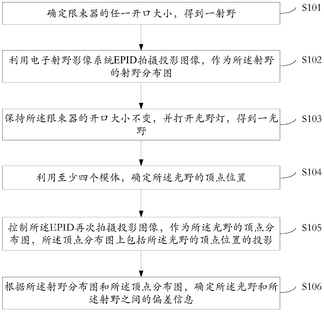
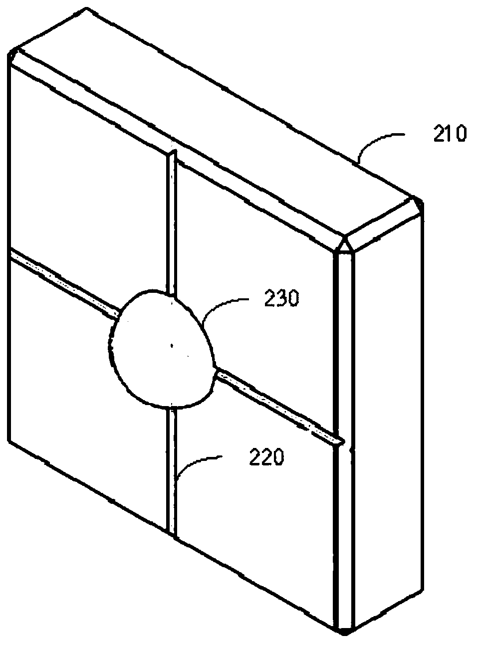
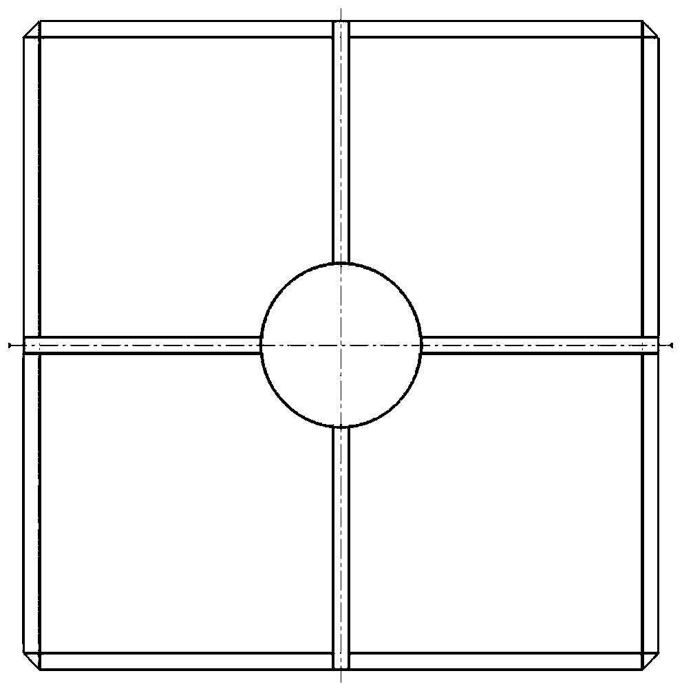
[0006] In view of this, this application provides a light field consistency detection phantom, method, device and equipment, which can freely detect the consistency of light fields, not limited to several fixed-sized fields, and solve the current Insufficient flexibility in light field consistency detection

Method used


Image

  • A light field consistency detection phantom, method, device and equipment
  • A light field consistency detection phantom, method, device and equipment
  • A light field consistency detection phantom, method, device and equipment

Examples


Embodiment Construction

[0061] The following will clearly and completely describe the technical solutions in the embodiments of the application with reference to the drawings in the embodiments of the application. Apparently, the described embodiments are only some of the embodiments of the application, not all of them. Based on the embodiments in this application, all other embodiments obtained by persons of ordinary skill in the art without making creative efforts belong to the scope of protection of this application.

[0062] The radiation field refers to the projection range of the X-rays emitted by the radiation device (such as an accelerator, etc.) in an imaging plane, and the light field refers to the visible light emitted by the head of the radiation device to simulate the light source, and the area defined in the imaging plane. Optical field consistency detection is an important performance index of medical equipment such as accelerators. It is related to the quality inspection and clinical u...


PUM


Abstract

Methods and devices for detecting consistency between an invisible radiation field and a visible light field are provided. In an example, the method includes: an invisible radiation field is obtained by controlling a size of an opening of a beam limiting device; a first projection image is captured by an Electron Portal Imaging Device (EPID) as a distribution map of the invisible radiation field; a visible light field is obtained by turning on a light field lamp without changing the size of the opening of the beam limiting device; a phantom is positioned at each of vertices of the visible light field; a second projection image is captured by the EPID as a vertex distribution map of the visible light field; and deviation information between the invisible radiation field and the visible light field is determined according to the distribution map of the invisible radiation field and the vertex distribution map of the visible light field.

Description

technical field [0001] The present application relates to the field of data processing, in particular to a light field consistency detection phantom, method, device and equipment. Background technique [0002] In medical radiotherapy technology, before or during radiotherapy for patients, it is necessary to use various medical imaging equipment to monitor tumors and normal organs in real time, so that the X-ray irradiation can be adjusted in real time according to the change of tumor position, so that The X-ray radiation field closely "follows" the target area, precisely irradiates the tumor position, and achieves the purpose of radiation therapy in the true sense. [0003] However, X-rays are invisible to the naked eye. If you want to accurately irradiate the tumor with X-rays, you need to introduce a light field of visible light to assist X-ray positioning. Therefore, it is required that the light field of visible light and the X-ray field keep a high degree of coincidenc...

Claims


Application Information

Patent Timeline
Patent Type & Authority Patents(China)
IPC IPC(8): A61N5/10
CPCA61N5/10A61N5/1049A61N2005/1054A61N2005/1092A61N5/1075A61N2005/1056A61N2005/1076
Inventor 徐晗姜志超张林李明
Owner NEUSOFT MEDICAL SYST CO LTD
Learn More