Hybrid transmission gearbox

A hybrid transmission and gearbox technology, applied in the gearbox field, can solve problems such as low transmission efficiency

Inactive Publication Date: 2018-02-13
RG PETRO MACHINERY GROUP
View PDF2 Cites 0 Cited by
  • Summary
  • Abstract
  • Description
  • Claims
  • Application Information

AI Technical Summary

Problems solved by technology

The disadvantage is that the transmission efficiency is low

Method used


Image

  • Hybrid transmission gearbox

Examples


Embodiment Construction

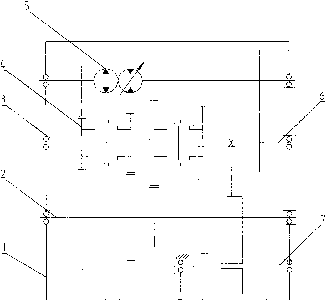
[0009] Referring to the accompanying drawings, a hybrid transmission gearbox has a structure comprising: a casing 1, in which an intermediate shaft 2, an input shaft 3, a gear set 4, an integrated pump motor 5, an output shaft 6 and a reverse gear are arranged. Axis 7. Inside the box body 1, the power enters the box body through the input shaft 3 and is divided into two roads, and one road passes through the gear set 4, the intermediate shaft 2, the reverse gear shaft 7, and the output shaft 6 to output five forwards and one reversed six gears. Mechanical transmission; the other channel transmits and outputs power through the integrated pump motor 5 and output shaft 6, and the output speed and torque are continuously and steplessly adjustable.


PUM


Abstract

The invention belongs to the technical field of gearboxes and provides a hybrid transmission gearbox. By means of the hybrid transmission gearbox, mechanical transmission and static hydraulic transmission are combined in parallel and are integrated in one shell. Power enters a box body through an input shaft of the gearbox and then is divided into two ways; one way is gear mechanical transmission,and six gears including five positive gears and one reverse gear are output after transmission of a connecting sleeve, a gear pair, an intermediate shaft and a reverse shaft is conducted; and the other way drives an integrated pump motor through a gear. The integrated pump motor is a set of closed static hydraulic transmission system, wherein the system converts input power into pressure oil, andthe pressure oil then enters the motor to be converted into mechanical torque to be output. Due to the fact that the inclination angle of an oblique plate of the pump and the oil pressure are controlled, the output rotating speed and the torque can be adjusted, and the output rotating speed and torque are steplessly adjusted continuously.

Description

technical field [0001] The invention relates to the technical field of gearboxes, in particular to a hybrid transmission gearbox. Background technique [0002] The transmission system of the current walking machinery equipment is divided into two types, one is a mechanical transmission device, and the other is a hydrostatic transmission. [0003] The mechanical transmission device is composed of a hydraulic torque converter and a gear box. The advantage is that the transmission efficiency is high. However, since the hydraulic mechanical transmission device is a step-variable transmission, it cannot realize stepless transmission and cannot provide continuously changing torque. Large and stable torque cannot be provided. [0004] The hydrostatic transmission adopts a closed oil circuit, which is composed of oil pumps, pipelines, control valves and hydraulic motors. The working principle is that the engine drives the oil pump to increase the pressure of the working oil in the...

Claims


Application Information

Patent Timeline
IPC IPC(8): F16H47/02
CPCF16H47/02
Inventor 刘海伟蔡婧华丹丹马向南沈晓博韩小启张江河赵东海马进生
Owner RG PETRO MACHINERY GROUP
Why Eureka
Try Eureka