
Test module, system and test method for testing damping valve of oil damper

A technology of testing modules and damping valves, which is applied in the testing of machines/structural components, shock absorbers, mechanical valves, etc., which can solve problems such as inconvenient, infeasible, and non-energy-saving, and achieve convenient and accurate movement and management of equipment Effect of test temperature and accurate temperature control

Active Publication Date: 2018-02-09
DONGGUAN UNIV OF TECH
View PDF8 Cites 15 Cited by
  • Summary
  • Abstract
  • Description
  • Claims
  • Application Information

AI Technical Summary

Problems solved by technology

[0006] (2) A complete set of hydraulic system including hydraulic pumps, various hydraulic control valves and oil tanks is used to supply oil to the piston valve, so the system is complex and bulky
Because at low temperatures, such as below -30°C, general hydraulic pumps can no longer effectively absorb oil, and many hydraulic control valves and pipelines cannot work normally, let alone carry out relevant tests effectively and accurately; moreover, in high and low temperature tests In the process, it is inconvenient and not energy-saving to control the temperature of the hydraulic oil of the entire hydraulic system
[0008] (4) Only the "flow-pressure characteristics" of the piston valve can be tested, and its dynamic characteristics and indicators such as response, opening and closing cannot be tested
[0009] In order to test the dynamic characteristics of the oil pressure shock absorber damper valve in high and low temperature environments, the conventional test method in the prior art is not feasible, so it is necessary to invent a new test principle and test module, automatic measurement and control system and experiment method

Method used


Image

  • Test module, system and test method for testing damping valve of oil damper
  • Test module, system and test method for testing damping valve of oil damper
  • Test module, system and test method for testing damping valve of oil damper

Examples


Embodiment Construction

[0048] The present invention will be described in further detail below in conjunction with the accompanying drawings and specific embodiments.

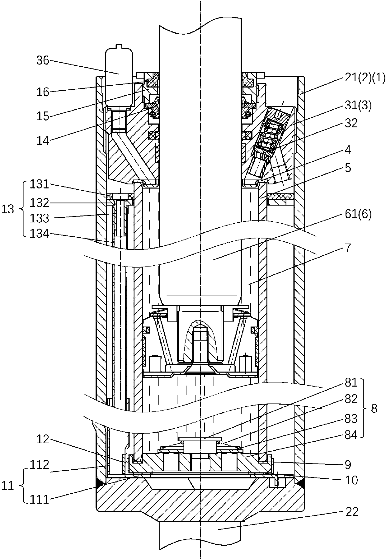
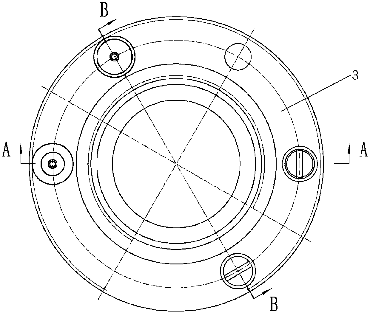
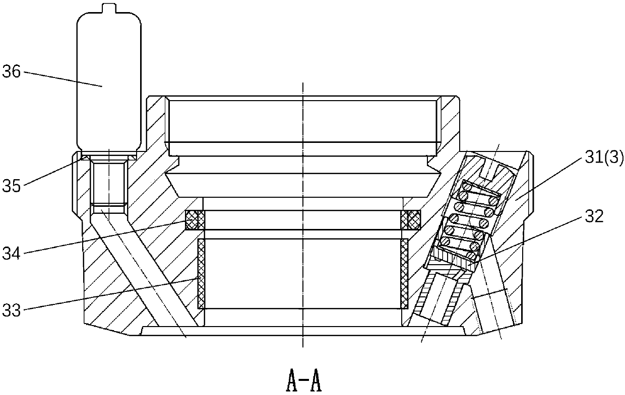
[0049] Figure 1 to Figure 8 It shows an embodiment of a testing module of the present invention for testing the dynamic characteristics of a damper valve of an oil pressure shock absorber. The test module includes oil storage cylinder assembly 2, guide assembly 3, guide exhaust plate 4, pressure cylinder 5, piston-piston rod assembly 6, hydraulic oil 7, bottom valve assembly 8, pressure cylinder gasket 9, bottom Valve gasket 10, oil guide plate assembly 11, magnet 12, oil return assembly 13, skeleton oil seal 14, screw cap 15 and dustproof ring 16. The oil deflector assembly 3 is connected to the oil storage cylinder assembly 2, the oil deflector assembly 3 is placed at the bottom of the cylinder barrel of the oil storage cylinder assembly 2, the bottom valve gasket 10 is placed on the base of the oil deflector assembly 11, and the ...


PUM


Abstract

The invention provides a test module, a system and a test method for testing the dynamic characteristic of the damping valve of an oil damper at high / low temperature. The test module includes an oil storage cylinder component, a guide component, a guide exhaust plate, a pressure cylinder, a piston-piston rod component, hydraulic oil, a bottom valve component, a pressure cylinder gasket, a bottom valve gasket, an oil guide plate component, a magnet, an oil return component, a framework oil seal, a screw cap, and a dustproof ring. The test module integrates the hydraulic oil, an oil supply mechanism, a tested damping valve and a sensor through the principle of integrated design. The entire test module can be placed in a high / low-temperature box. The problem on how to control the oil temperature of the tested damping valve can be conveniently, effectively and accurately solved. An automatic test system based on the test module and a related test method are further provided.

Description

technical field [0001] The invention relates to an integrated test module, an automatic measurement and control system and a test method capable of performing dynamic characteristic tests on oil pressure shock absorber damping valves in high and low temperature environments, belonging to hydraulic component test equipment and hydraulic component test technology , Technical field of hydraulic damper product testing. Background technique [0002] Oil shock absorber is an important part of modern railway vehicles such as high-speed rail, which plays an important role in the motion stability and comfort of the vehicle system, and the damper valve is a key component inside the oil pressure The damping characteristics of the compression shock absorber play a decisive role. Therefore, it is of great significance to test the dynamic characteristics of the oil pressure shock absorber damper valve and understand its performance and index. In addition, with the development of modern ...

Claims


Application Information

Patent Timeline
Patent Type & Authority Applications(China)
IPC IPC(8): G01M13/00
CPCG01M13/00F16F2230/0047F16F9/34F16F9/3264G01M13/003F16F9/185F16F9/3242F16F2222/12G01M17/04
Inventor 王文林周梓荣曹晓畅尹玲林小夏
Owner DONGGUAN UNIV OF TECH
Learn More