Eureka AIR delivers breakthrough ideas for toughest innovation challenges, trusted by R&D personnel around the world.

Air-duct air conditioner

An air conditioner and duct-type technology, which is applied in the field of duct-type air conditioners, can solve problems such as unrealizable, and achieve the effect of increasing air suction, suppressing turbulence and noise

Pending Publication Date: 2018-02-09
DAIKIN IND LTD
View PDF9 Cites 1 Cited by
  • Summary
  • Abstract
  • Description
  • Claims
  • Application Information

AI Technical Summary

Problems solved by technology

[0004] However, when using Figure 8 , Figure 9 In the case of the ducted air conditioner shown, if the adjacent space needs to be air-conditioned at the same time, it cannot be realized. Therefore, it is necessary to design a new form of ducted air conditioner so that a single ducted air conditioner can satisfy the needs of users. The air conditioning needs of a separate space can also meet the simultaneous use of two spaces

Method used


Image

  • Air-duct air conditioner
  • Air-duct air conditioner
  • Air-duct air conditioner

Examples


Embodiment approach 1

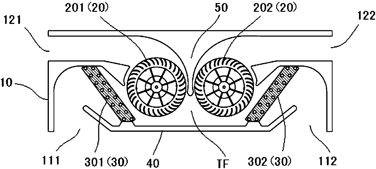
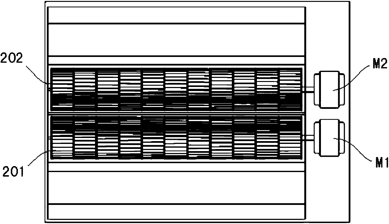
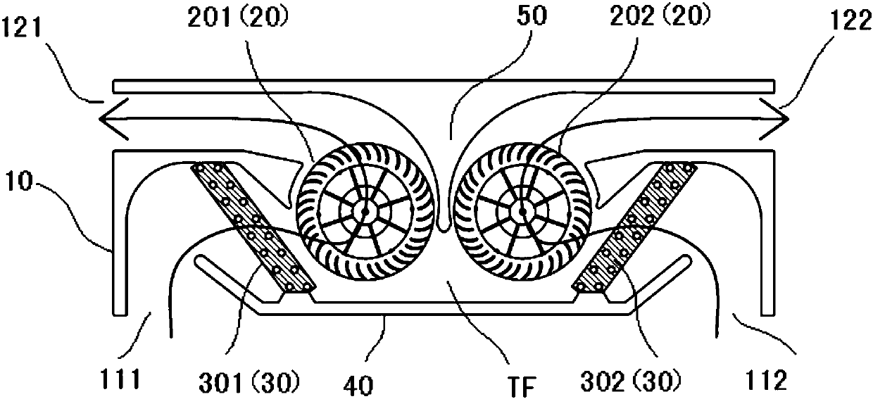
[0093] Refer below Figure 1A ~ Figure 1D , the duct-type air conditioner according to Embodiment 1 of the present invention will be described, wherein, Figure 1A is a cross-sectional view schematically showing the structure of the ducted air conditioner according to Embodiment 1 of the present invention, Figure 1B It is a plan view showing the structure of the ducted air conditioner according to Embodiment 1 of the present invention, and shows a state in which a part of the housing is removed to expose the first fan, the second fan, etc., Figure 1C ~ Figure 1E It is a cross-sectional view schematically showing the operating state of the ducted air conditioner according to Embodiment 1 of the present invention.

[0094] In this embodiment, if Figure 1A As shown, the ducted air conditioner includes a casing 10, and a fan 20 and a heat exchanger 30 are arranged inside the casing 10, wherein the casing 10 has a first air inlet 111, a second air inlet 112, a first air inlet ...

example 2

[0120] In the above Embodiment 1, as Figure 1H As shown, a third heat exchanger 303" can also be set between the first fan and the first air outlet in the first air flow path, and between the second fan and the second air outlet in the second air flow path Fourth heat exchanger 304".

[0121] Here, the third heat exchanger 303" is installed obliquely with respect to the bottom surface of the casing in the first air flow path, and the fourth heat exchanger 304" is installed obliquely with respect to the bottom surface of the casing in the second air flow path. .

[0122] According to this modified example, basically the same technical effect as that of the first embodiment described above can be achieved.

[0123] In addition, according to this modified example, the heat exchange effect can be improved when operating in the dual air outlet mode or the single air outlet mode.

[0124]

[0125] In Embodiment 1 above, a vent damper switchable between the state of opening the...

example 5

[0137] In the above Embodiment 1, as Figure 1N As shown, a first auxiliary air inlet 113 on the side of the first fan and a second auxiliary air inlet 114 on the side of the second fan may also be opened on the side of the casing.

[0138] According to this modified example, basically the same technical effect as that of the first embodiment described above can be achieved.

[0139] In addition, according to this modified example, by providing the first auxiliary air inlet 113 and the second auxiliary air inlet 114 , the suction air volume can be increased, thereby improving the performance.


PUM


Abstract

Disclosed is an air-duct air conditioner. According to the air-duct air conditioner, air regulating can be conducted on one of two spaces individually, and air regulating can be conducted on the two spaces simultaneously. The air-duct air conditioner comprises a shell body, a fan and a heat exchanger are arranged in the shell body, a first air inlet, a second air inlet, a first air opening and a second air opening are formed in the shell body, the fan comprises a first fan and a second fan, and the heat exchanger comprises a first heat exchanger and a second heat exchanger. The first fan and the second fan are arranged between the first heat exchanger and the second heat exchanger. In the shell body, the first heat exchanger and the first fan are arranged in a first air flow path from thefirst air inlet to the first air opening. The second heat exchanger and the second fan are arranged in a second air flow path from the second air inlet to the second air opening.

Description

technical field [0001] The invention relates to an air duct type air conditioner. Background technique [0002] Figure 7 It is a cross-sectional view schematically showing an example of a ducted air conditioner (sometimes called a ducted air conditioner indoor unit or a ducted unit) in the prior art. This ducted unit can generally only perform air conditioning for a single space. To perform air conditioning for two spaces at the same time, it is necessary to install an air duct machine in each of the two spaces to adjust the air in the space, which will increase the purchase and use costs of users. [0003] In response to the above problems, it was also proposed that Figure 8 , Figure 9 The air duct machine shown includes two air outlets X1 and X2, and the above air outlets X1 and X2 are interchangeable between the air return port and the air outlet by controlling the turning of the fan (refer to arrows A, A', B, B') , one air duct machine can meet the air conditioning...

Claims


Application Information

Patent Timeline
Patent Type & Authority Applications(China)
IPC IPC(8): F24F1/00F24F13/06F24F13/20F24F11/74
CPCF24F1/0014F24F1/0022F24F1/0033F24F1/0059F24F13/06F24F13/20
Inventor 毛本甲孙洁
Owner DAIKIN IND LTD
Why Eureka
Eureka Blog
Learn More