Axial flow blower

An axial flow fan and airflow technology, which is applied in axial flow pumps, mechanical equipment, machines/engines, etc., can solve the problems of turbulent airflow, increased noise, and increased pressure difference, so as to suppress turbulent flow and realize noise reduction , low noise effect

Active Publication Date: 2013-01-23
MITSUBISHI ELECTRIC CORP
View PDF8 Cites 10 Cited by
  • Summary
  • Abstract
  • Description
  • Claims
  • Application Information

AI Technical Summary

Problems solved by technology

[0006] However, in the technique described in Patent Document 1, the blades (blades) are formed in such a shape that their horizontal angles gradually increase toward the outer peripheral side, and therefore, the airflows toward the inner peripheral side of the fan interfere with each other to generate turbulence in the airflow. flow, resulting in increased noise
In addition, in the technology described in the above-mentioned Patent Document 1, the pressure difference between the positive pressure surface and the negative pressure surface becomes large near the outer periphery of the blade, and a large-scale and unstable tip vortex is generated, which also leads to an increase in noise.

Method used


Image

  • Axial flow blower
  • Axial flow blower
  • Axial flow blower

Examples


Embodiment Construction

[0018] Hereinafter, embodiments of the present invention will be described based on the drawings.

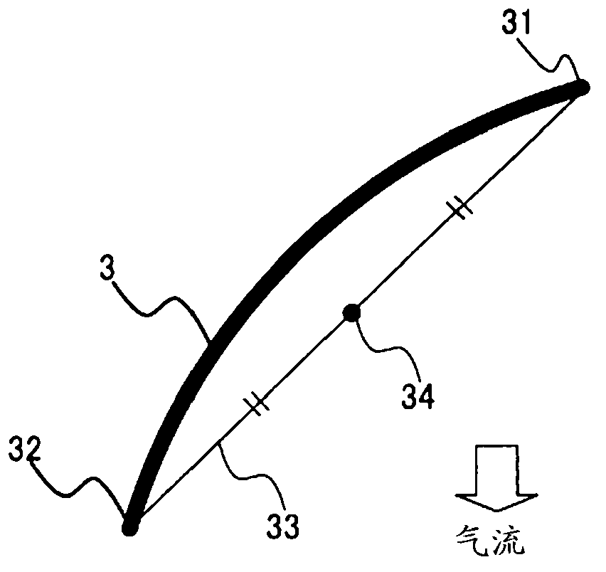
[0019] figure 1 It is a perspective view which shows the structure of the axial flow fan of this embodiment. figure 2 It is a front view showing the structure of the axial flow fan of this embodiment. image 3 yes means figure 2 Plane development of the I-I section of . Figure 4 It is a projected view showing the chord centerline of the axial flow fan according to the present embodiment and a blade cross section taken by a curved surface including the chord centerline and parallel to the rotation axis, projected on a plane including the rotation axis. Figure 5 It is an explanatory drawing for demonstrating the flow field of the axial flow fan of this embodiment. Image 6 It is a graph showing the relationship between Ro / (Rt-Rb) and the standard noise reduction amount in the axial flow fan according to the present embodiment. Figure 7 It is a graph showing the relations...


PUM


Abstract

Provided is an axial flow blower wherein noise is reduced by ensuring the effective work of blades and suppressing the blade tip vortex. The axial flow blower is formed so that a chord center line (37) extending so as to connect chord center points (34) from the inner peripheral end to the outer peripheral end of a blade (3), is curved and projected toward the downstream side in the entire region.

Description

technical field [0001] The present invention relates to an axial flow fan widely used in, for example, air conditioners, ventilators, and the like. Background technique [0002] Axial flow fans are widely used in air-conditioning equipment and ventilation equipment to achieve low noise. Therefore, various axial flow fans for reducing noise have been proposed. As such an axial flow fan, "an axial flow fan in which a plurality of blades are provided on the outer periphery of a cylindrical hub portion is disclosed, wherein the blades are formed in a shape along The cross-section of any surface extending radially through the blade root in contact with the hub portion from the rotation center line is bent toward the outer peripheral portion side at any portion and directs the outer peripheral portion in the air blowing direction, and, as the direction On the outer peripheral side, the horizontal angle becomes gradually larger" (for example, refer to Patent Document 1). [0003...

Claims


Application Information

Patent Timeline
Patent Type & Authority Applications(China)
IPC IPC(8): F04D29/38
CPCF04D29/384F05D2240/307F04D19/002
Inventor 中岛诚治吉濑幸司堀内启史
Owner MITSUBISHI ELECTRIC CORP
Why Eureka
Try Eureka