Fabricated special-shaped column joint and construction method
A special-shaped column and prefabricated technology, applied in protective buildings/shelters, building components, earthquake-proof, etc., can solve the problem of being unable to withstand earthquake residual energy, and achieve the effect of high cost performance, simple structure, and reduced damage
- Summary
- Abstract
- Description
- Claims
- Application Information
AI Technical Summary
Problems solved by technology
Method used
Image

Examples
Embodiment 1
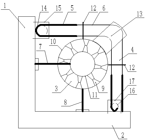
[0034] Such as Figure 9 As shown, an assembled special-shaped column node includes a special-shaped column 1 and a beam 2 on both sides of the special-shaped column, and a joint energy dissipation device is provided at the connection between the special-shaped column 1 and the beam 2 on each side, such as the special-shaped column 1 It is a column with a cross-section; a limit energy dissipation device is provided at the two angles between the special-shaped column and the beam; for example Figure 10 As shown, the beams 2 on both sides of the special-shaped column are connected by tensioned prestressed steel rods 40, and the node energy dissipation device includes the third connecting steel plate 31, the fourth connecting steel plate 32 and the rubber pad 37, the third connecting steel plate 31 and the fourth connecting steel plate The four connecting steel plates 32 face each other, and the rubber pad 37 is located between the third connecting steel plate 31 and the fourth ...
Embodiment 2
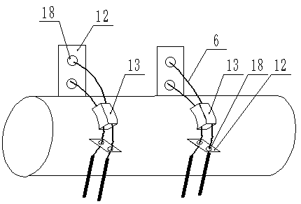
[0048] Such as Figure 8 As shown, the difference between this embodiment and Embodiment 1 is that two limiting plates 12 are welded on the outer wall of the outer cylinder 10, and the angle between the two limiting plates 12 is 90 degrees, and one of the limiting plates 12 Horizontally welded on the side of the outer cylinder 10 away from the special-shaped column 1, another limiting plate 12 is vertically welded on the side of the outer cylinder 10 away from the beam 2, and the two limiting plates 12 are respectively provided with two limiting holes 18, Two limiting holes 18 are arranged in the axial direction of the outer cylinder 10 , the axes of the limiting holes 18 are parallel to the axis of the outer cylinder 10 , and the two sections of the second chain 6 respectively pass through one limiting hole of the two limiting plates 12 .
Embodiment 3
[0050]The difference between this embodiment and Embodiment 1 is that this specific embodiment uses steel strands instead of tensioned prestressed steel rods, and the rubber pad 37 is located between the third connecting steel plate 31 and the fourth connecting steel plate 32. The rubber pad 37 is composed of two layers of rubber pads, the two layers of rubber pads are fixed between the third connecting steel plate 31 and the fourth connecting steel plate 32 through the fixing device, and the first steel cylinder 42 and the second steel cylinder 43 are respectively in the two layers of rubber pads , and the other structures are the same.
[0051] The sliding limit guide rail 13 in the foregoing embodiments can be a cage with multiple layers of balls or rollers, the cage is fixed on the outer cylinder 10, and the second chain 6 passes through the middle of the two layers of balls or rollers.
[0052] The working principle of the assembled special-shaped column node of the prese...
PUM
 Abstract
Description
Claims
Application Information
 - R&D
- Intellectual Property
- Life Sciences
- Materials
- Tech Scout
- Unparalleled Data Quality
- Higher Quality Content
- 60% Fewer Hallucinations
Browse by: Latest US Patents, China's latest patents, Technical Efficacy Thesaurus, Application Domain, Technology Topic, Popular Technical Reports.
© 2025 PatSnap. All rights reserved.Legal|Privacy policy|Modern Slavery Act Transparency Statement|Sitemap|About US| Contact US: help@patsnap.com