Multi-stage exhaust gas turbocharger

A technology of exhaust gas turbine and supercharger, which is applied to gas turbine devices, non-variable pumps, non-volume pumps, etc., to achieve the effects of increased efficiency, good cooling, and less structural space

Active Publication Date: 2020-08-21
AVL LIST GMBH
View PDF15 Cites 0 Cited by
  • Summary
  • Abstract
  • Description
  • Claims
  • Application Information

AI Technical Summary

Problems solved by technology

[0009] Disadvantages of all known solutions are, on the one hand, the high temperature of the compressed air flow and, on the other hand, the resulting thermal load on the turbocharger housing and the components used

Method used


Image

  • Multi-stage exhaust gas turbocharger
  • Multi-stage exhaust gas turbocharger
  • Multi-stage exhaust gas turbocharger

Examples


Embodiment Construction

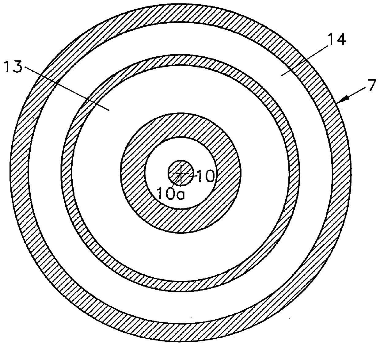
[0057] figure 1 A compressor 1 a of an exhaust gas turbocharger 2 is shown, which has a first compressor stage 3 and a second compressor stage 4 . A compressor rotor 9 configured with rotor wheels 5 , 6 on both sides and arranged in the compressor housing part 7 of the exhaust gas turbocharger housing 8 is mounted rotatably in the exhaust gas turbocharger housing 8 about an axis of rotation 10 a The shaft 10 of the exhaust gas turbocharger 2 is non-rotatably connected to a turbine rotor (not further shown) of the exhaust gas turbine of the exhaust gas turbocharger 2 . The compressor housing part 7 has an axial compressor inlet 11 connected to a not further shown fresh air line for taking in fresh air and a connection to the charge air line of the internal combustion engine indicated by reference numeral 12 for Compressor outlet for charge air. The flow of air is indicated by arrow S.

[0058] The compressor stage outlet 13 from the first compressor stage 3 is arranged in th...


PUM


Abstract

Disclosed is a multi-stage turbocharger (2) for an internal combustion engine, said turbocharger comprising an exhaust gas turbine (16) having at least one turbine impeller, and a compressor (1a) having a first compressor stage (3) and a second compressor stage (4), said compressor comprising at least one compressor impeller (9) arranged in a compressor housing part (7) of the turbocharger housing (8), wherein: the turbine impeller and the compressor impeller (9) are arranged on a common shaft (10) that is rotatably mounted in the turbocharger housing (8) about an axis of rotation (10a); the compressor housing part (7) has an axial compressor inlet (11) for attaching to a fresh air pipe; an intercooler (15) is arranged between the first compressor stage (3) and the second compressor stage (4) with respect to flow; and wherein the intercooler (15) is fluidically connected to at least one compressor stage outlet (13) from the first compressor stage (3) and to at least one compressor stage inlet (14) into the second compressor stage (4). In order to reduce the thermal load of a multi-stage turbocharger (2), the intercooler (15) has a cooler housing (16) connected to the compressor housing part (7) and the intercooler (15) is directly attached to the at least one compressor stage outlet (13) and to the at least one compressor stage inlet (14), wherein at least one compressor stage outlet (13) from the first compressor stage (3) and at least one compressor stage inlet (14) into the second compressor stage (4) are arranged in the region of a first end face (7a) of the compressor housing part (7).

Description

technical field [0001] The invention relates to a multi-stage exhaust gas turbocharger, in particular a high-pressure turbocharger, for an internal combustion engine, comprising an exhaust gas turbine with at least one turbine rotor and a compressor with a first A compressor stage and a second compressor stage, the compressor comprising at least one compressor rotor arranged in the compressor housing part of the exhaust gas turbocharger housing, wherein the turbine rotor and the compressor rotor are arranged in the exhaust gas turbocharger on a common shaft mounted rotatably about an axis of rotation in the compressor housing, wherein the compressor housing part has an axial compressor inlet for connection to the fresh air line, wherein the intercooler is flow-wise arranged at the second between a compressor stage and a second compressor stage, and the intercooler is in fluid connection with at least one compressor stage outlet from the first compressor stage, and with at leas...

Claims


Application Information

Patent Timeline
Patent Type & Authority Patents(China)
IPC IPC(8): F04D29/58F02C7/143F04D29/42F02C6/12
CPCF02C6/12F04D17/12F04D29/5826F02C7/143F04D29/4206F05D2220/40F05D2260/211
Inventor T·奥本诺斯
Owner AVL LIST GMBH
Why Eureka
Try Eureka