Eureka AIR delivers breakthrough ideas for toughest innovation challenges, trusted by R&D personnel around the world.

Illumination device and head-up display device

A lighting device and diffuser technology, which is applied to lighting devices, lighting device parts, lighting and heating equipment, etc., can solve the problems of increasing the number of LED lamps, increasing heat dissipation, and increasing heat dissipation in backlight devices.

Inactive Publication Date: 2018-02-06
HAYASHI TELEMPU CO LTD
View PDF8 Cites 5 Cited by
  • Summary
  • Abstract
  • Description
  • Claims
  • Application Information

AI Technical Summary

Problems solved by technology

In the case of high-output LEDs using a small number of lamps, the amount of lost light increases, which leads to an increase in heat dissipation, an increase in the size of the heat sink, and an increase in the size of the backlight unit. In the case of low-output LEDs using many lamps In the case of LEDs, the number of locations where light loss occurs increases, so if a structure that does not reduce the generation of light loss itself as in the prior art of Patent Documents 1 to 4 is adopted, the number of LED lamps will further increase, and as a result Yes, it leads to an increase in heat dissipation, an increase in the size of the heat sink, and an increase in the size of the backlight unit

Method used


Image

  • Illumination device and head-up display device
  • Illumination device and head-up display device
  • Illumination device and head-up display device

Examples


Embodiment Construction

[0039] Embodiments of the present invention will be described below with reference to the drawings. In addition, the same code|symbol in each drawing represents the same or a corresponding part, and when there is no description of a change etc. especially, description about it is abbreviate|omitted suitably.

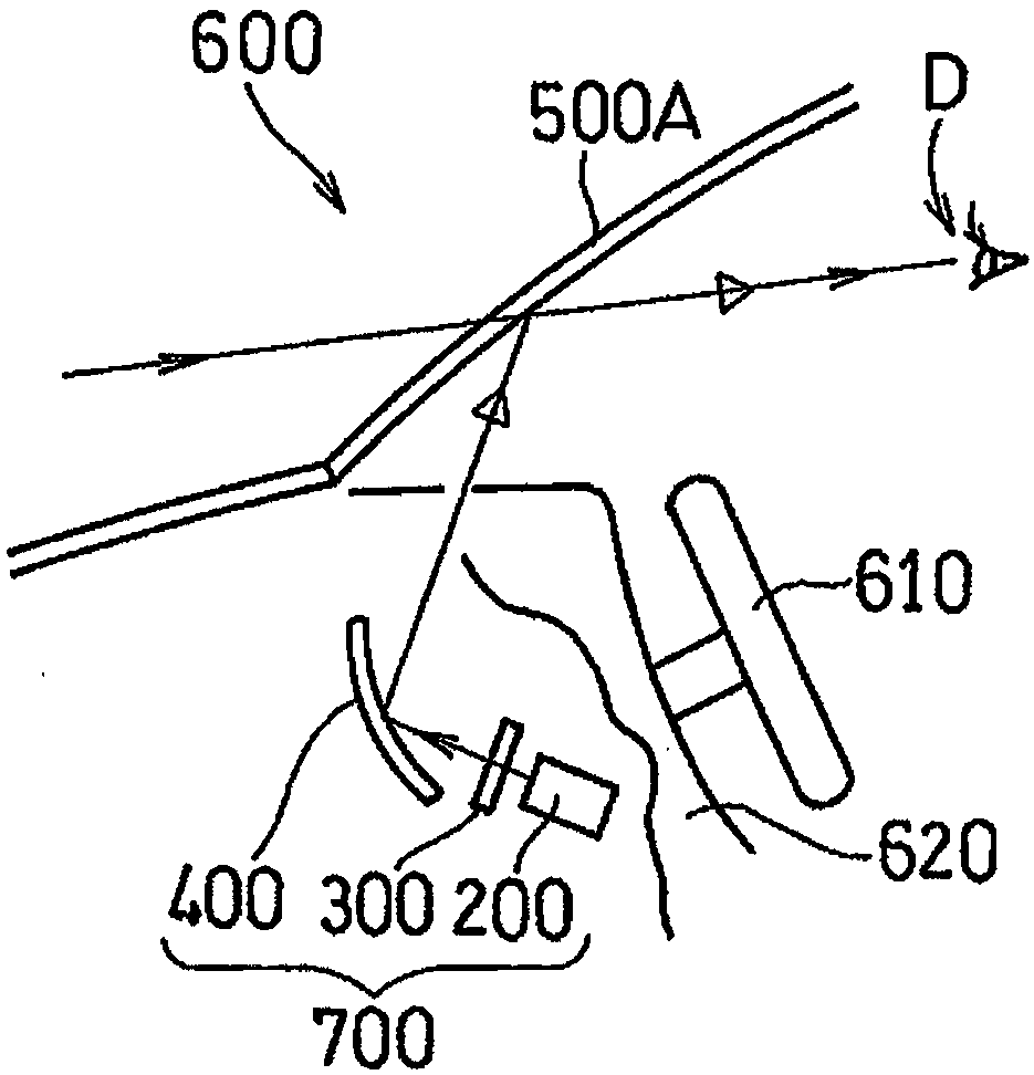
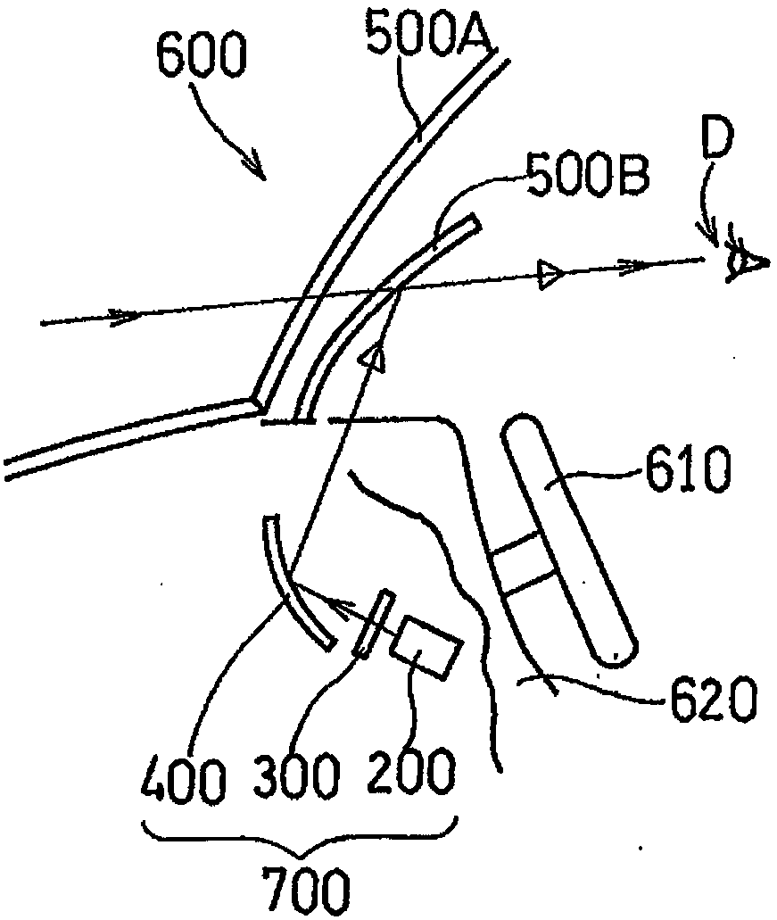
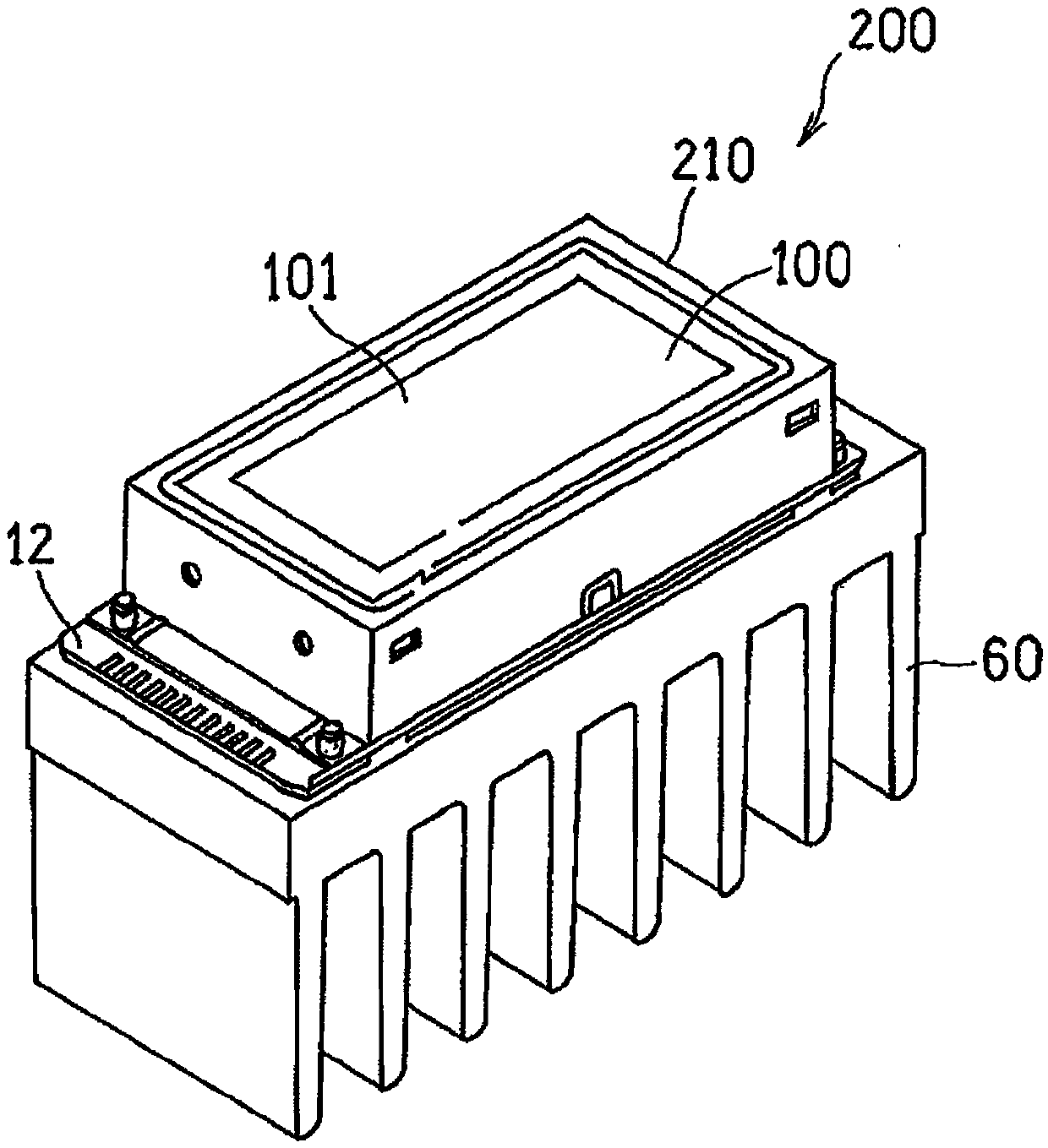
[0040] figure 1 A schematic side view of a head-up display (HUD) device 700 mounted on a vehicle 600 according to one embodiment is shown. The HUD device 700 includes a lighting device 100 ( image 3 ) of the backlight 200, the projection unit 300 and the optical system 400. The HUD device 700 is mounted, for example, inside the dashboard of the vehicle 600 near where the steering wheel 610 or an instrument panel (not shown) is provided. Specifically, the backlight 200 such as image 3 stereogram and Figure 4 As shown in the front view of , for example, it is composed of a lighting device 100 and a heat sink 60 covered by a black top frame 210 so that the light em...


PUM


Abstract

The invention provides an illumination device and a head-up display device. The illumination device (100) comprises a plurality of light sources (10), which are arranged in a two dimensional matrix and give off illumination light (L1) to an opposite direction; a condensing lens (20), which is arranged on the exit surface of the light sources (10) and comprises multiple convex lens parts (22) corresponding to the light sources (10) respectively, wherein the convex lens parts (22) converge the illumination light (L1) emitted by the light sources (10); and a collimating lens array (30), which isarranged on the exit surface of the condensing lens (20) and is provided with multiple protruded light exiting surfaces (32) corresponding to the convex lens parts (22). Through the collimating lens array (30), the illumination light (L1) from neighbored convex lens parts (22) is emitted from the protruded light exiting surfaces (32) in parallel light that is not overlapped with each other.

Description

technical field [0001] The present invention relates to a lighting device having a plurality of light sources and a head-up display device including the lighting device. Background technique [0002] Conventionally, there is known a head-up display device (Head Up Display; hereinafter also referred to as a HUD device) in which an original display image formed by transmitting illumination light through a projection member such as a transmissive liquid crystal panel (LCD) is A display image shaped by magnification or the like by a predetermined optical system is projected on a display member such as a windshield of a moving body (for example, a vehicle) for display. The HUD device is mounted on a vehicle such as an automobile, and projects the above-mentioned display image in the field of view of the driver or passenger as an observer during driving. The projection part displays the flat LCD data showing the original image, and the illumination light The display original imag...

Claims


Application Information

Patent Timeline
IPC IPC(8): G02B27/01F21V5/00F21Y115/10
CPCF21V5/007F21Y2115/10G02B27/0101
Inventor 小山润佐佐木修一田中克周
Owner HAYASHI TELEMPU CO LTD
Why Eureka
Eureka Blog
Learn More