Forming cavity and method of making a forming cavity

A cavity and external forming technology, applied in the direction of additive manufacturing, process efficiency improvement, absorbent pads, etc., can solve the problems of large industrial investment, the possibility of limiting the difference in the compactness of the absorbent layer, and the high cost of the grid support structure

Inactive Publication Date: 2020-09-08
吉地美股份公司
View PDF10 Cites 0 Cited by
  • Summary
  • Abstract
  • Description
  • Claims
  • Application Information

AI Technical Summary

Problems solved by technology

[0022] One disadvantage is that the cost of the grid-like support structure is very high, making the production process required to make the grid-like support structure costly and requiring large industrial investments
[0025] Another problem with support structures made by the aforementioned methods is that the compactness and corresponding density of the absorbent layer in the area of ​​the forming cavity cannot be easily modified
However, the diameter of the micro-openings is primarily determined by the minimum diameter of the shredded material that needs to be held and therefore cannot be used to determine the desired density of the shaped sub-layers
[0026] This greatly limits the possibility of distinguishing the compactness of the absorbent layer inside the absorbent layer, a feature that is increasingly desired by the market for absorbent fillings

Method used


Image

  • Forming cavity and method of making a forming cavity
  • Forming cavity and method of making a forming cavity
  • Forming cavity and method of making a forming cavity

Examples


Embodiment Construction

[0059] In this specification, like elements common to the illustrated embodiments are indicated by like reference numerals.

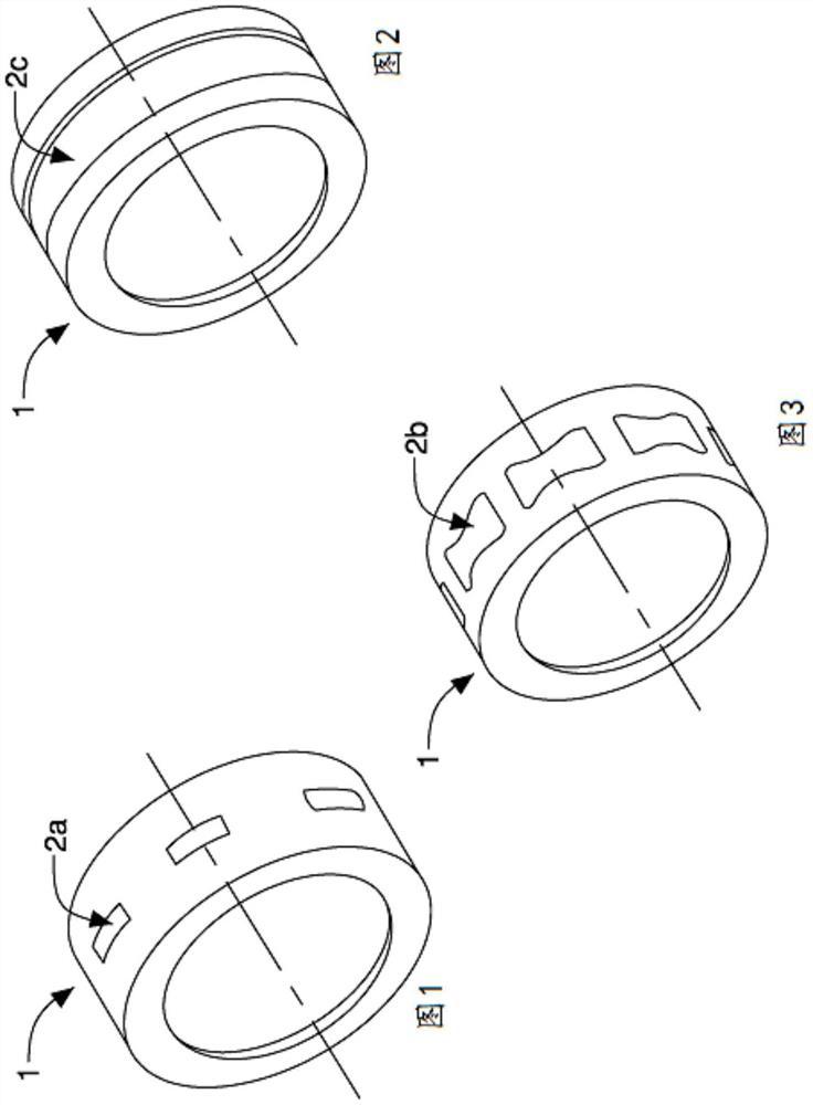
[0060] A forming device (not shown) for making absorbent fillings for hygiene articles comprises a forming conveyor for absorbent fillings. Already here Figure 1 to Figure 3 In particular, with reference to the prior art, 1 is used to represent the roller forming conveyor, and for the sake of brevity, details will not be repeated below.

[0061] The forming conveyor includes at least one forming cavity (not shown).

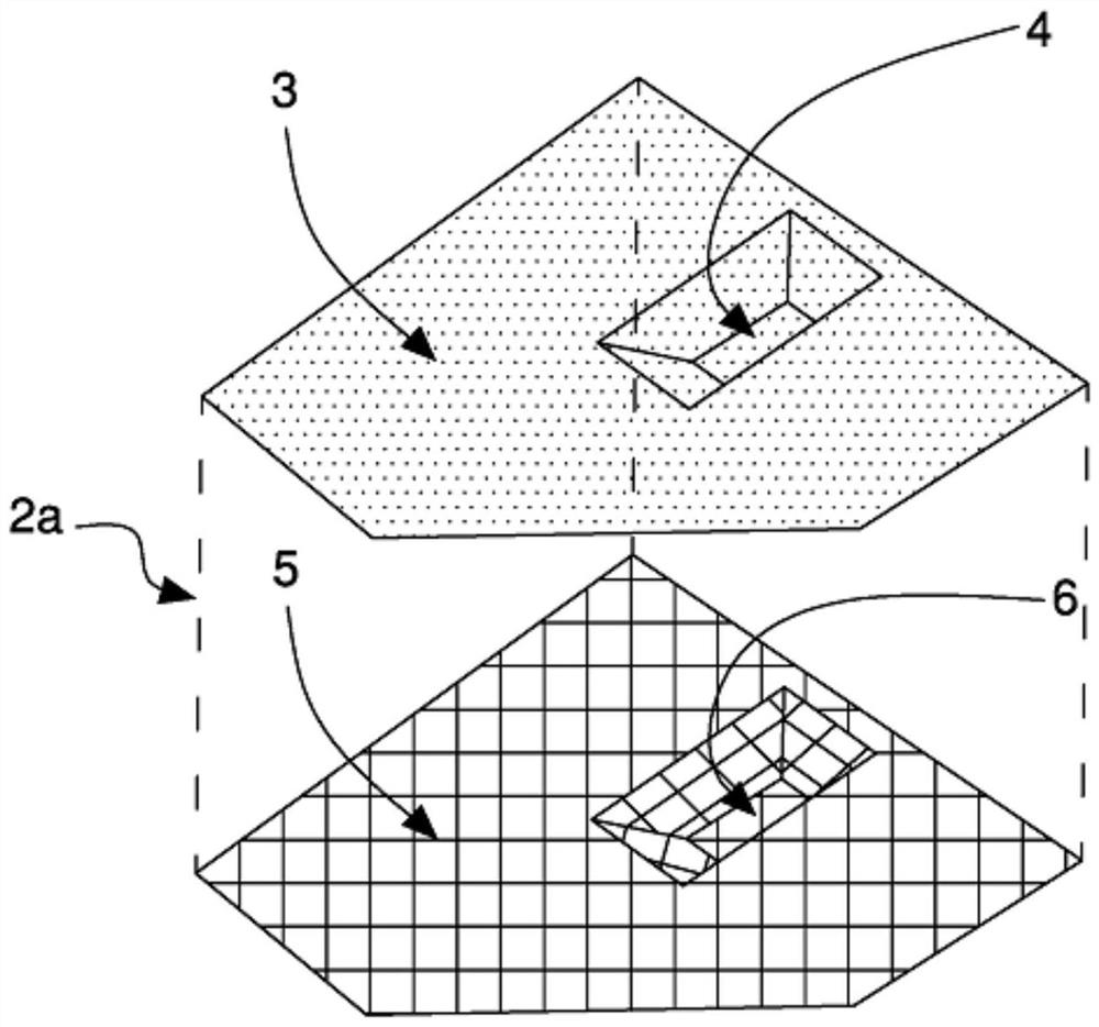
[0062] The forming cavity is adapted to receive particulate material and form therefrom an agglomerate of absorbent filling to be used as a hygiene article. The forming cavity comprises an outer forming substrate adapted to receive particulate material, made of metal mesh or sheet, provided with openings and having a shape conforming to the form of the absorbent filling to be made. exist Figure 4 The outer forming base indicated by 3 h...


PUM


Abstract

A forming cavity adapted to receive particulate material and form therefrom an agglomerate of absorbent fillings for use in hygiene articles, comprising: an outer forming matrix (3) adapted to receive said particulate material, said an outer forming matrix provided with openings and having a shape corresponding to the form of the absorbent filling to be produced; a grid-like support structure (10; 30) coupled to said outer matrix (3), to support the outer matrix (3) during suction of particulate material through the outer matrix (3), and includes a A curved outer surface (11) of the shape, an inner surface (12) opposite to said outer surface (11), a pair of larger sides (13) opposite to each other and a pair of smaller sides (14) opposite to each other, and through openings (17a, 17b, 18a, 18b) extending between said outer surface (11) and said inner surface (12) to allow gas to flow from said outer surface (11) to said inner surface (12) during suction the inner surface (12). A method for making a forming cavity, comprising: making at least one outer layer (15) of said support structure (10; 30) and at least one inner layer (16) of said support structure (10; 30), The outer layer and the inner layer are superimposed and have an outer opening (17a, 17b) and an inner opening (18a, 18b) bounded by an outer wall (19a, 19b) and an inner wall (20a, 20b), respectively, wherein the The outer openings (17a, 17b) and the inner openings (18a, 18b) are superimposed to define the through openings (17a, 17b, 18a, 18b); wherein the method further includes making an outer opening superimposed thereon One of said inner openings (18a, 18b) has at least one outer opening (17a, 17b) of different shape and / or size, and said outer wall ( 19a, 19b) and said inner wall (20a, 20b).

Description

technical field [0001] The present invention relates to a forming pocket for forming absorbent fillings for hygiene articles, the forming pocket comprising an outer forming matrix and a grid-like support structure coupled to the outer forming matrix, the outer forming The matrix is ​​adapted to receive particulate material and form agglomerates from the particulate material. [0002] The invention also relates to a method of fabricating a grid-like support structure forming a cavity by an additive manufacturing process. [0003] The invention is advantageously applied to a forming conveyor for shaping sanitary articles, the forming conveyor comprising a plurality of forming cavities adapted to form corresponding Absorbent aggregates, which will be mentioned below, without loss of generality. Background technique [0004] Hygienic articles, in particular baby diapers, sanitary napkins or adult incontinence products, are known to comprise a layer of absorbent filler, for exa...

Claims


Application Information

Patent Timeline
Patent Type & Authority Patents(China)
IPC IPC(8): A61F13/15B33Y80/00
CPCB33Y80/00A61F13/15626A61F13/15658B22F10/25Y02P10/25A61F13/15707A61F2013/15821B33Y10/00B22F5/007B29C33/3842
Inventor 马泰奥·皮安托尼瓦莱里奥·索利
Owner 吉地美股份公司
Why Eureka
Try Eureka