
UAV (unmanned aerial vehicle)-based river line detection system and method

A drone and line detection technology, applied in image data processing, instruments, calculations, etc., can solve the problems that the drone cannot always fly in the middle of the river, and cannot be adjusted in real time

Inactive Publication Date: 2018-02-02
BEIJING UNIV OF TECH +1
View PDF7 Cites 8 Cited by
  • Summary
  • Abstract
  • Description
  • Claims
  • Application Information

AI Technical Summary

Problems solved by technology

First of all, this method uses GPS for positioning. Due to large errors in navigation systems such as GPS, this method cannot realize that the UAV is always flying in the center of the river; second, in this method, the flight trajectory of the UAV is preset. Well, real-time adjustments cannot be made according to river conditions; third, in this method, only the drone transmits data to the ground station in one direction, and there is no interaction between the ground station and the drone

Method used


Image

  • UAV (unmanned aerial vehicle)-based river line detection system and method
  • UAV (unmanned aerial vehicle)-based river line detection system and method
  • UAV (unmanned aerial vehicle)-based river line detection system and method

Examples


Embodiment 1

[0108] system structure:

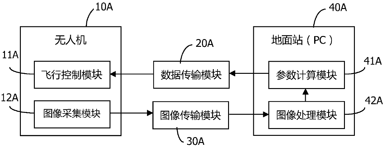
[0109] Such as figure 1 As shown, the UAV 10A includes a flight control module 11A and an image acquisition module 12A, wherein the function of the flight control module 11A is to control the flight attitude of the UAV, and the function of the image acquisition module 12A is to collect images through a camera.

[0110] The function of the data transmission module 20A is to send the parameters generated by the ground station to the flight control module 11A of the drone through radio frequency wireless communication.

[0111] The function of the image transmission module 30A is to transmit the image collected by the UAV image collection module 12A to the ground station (PC terminal) 40A.

[0112] The ground station 40A includes an image processing module 42A and a parameter calculation module 41A, wherein the function of the parameter calculation module 41A is to calculate the coordinates of the center of the river and the deviation value of the UAV...

Embodiment 2

[0156] system structure:

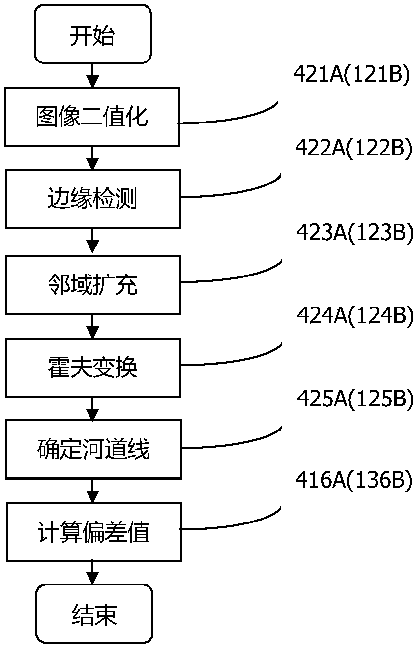
[0157] Such as figure 2 As shown, the UAV 10B includes a flight control module, an image acquisition module, an image processing module and a parameter calculation module, wherein the image acquisition module 11B is used to collect images through a camera. The function of the image processing module 12B is to process the image data collected by the image acquisition module to determine the position of the river line. The function of the parameter calculation module 13B is to calculate the coordinates of the center of the river channel and the deviation value of the UAV according to the processed image. The function of the flight control module 14B is to control the flight attitude of the drone.

[0158] The image acquisition module 11B erected by the UAV 10B performs image acquisition, and then sends the acquired image to the image processing module 12B through an image transmission data line (HDMI, etc.). The image processing module is generally...


PUM


Abstract

The invention discloses an UAV (unmanned aerial vehicle)-based river line detection system and method and belongs to the technical field of UAV delivery. The system comprises two modes, that is, a mode of interaction control between an UAV and a ground station, and a mode of output control based on the UAV, and the two modes are parallel technical schemes. In the first mode, the UAV transmits images to the ground station, the ground station carries out image processing and returns the processing result to flight control of the UAV through a data transmission device to finish a function; and inthe second mode, the UAV is provided with an image processing chip (a DSP chip), and the UAV finishes image acquisition, processing and data interaction work. The UAV can realize an autonomous cruisefunction without any manual operation; the method can realize cruise according to actual conditions of a river, and the case of flying away from the river cannot occur; and the method is higher in precision than a GPS navigation mode.

Description

technical field [0001] The invention relates to a river line detection system and method, in particular to an electronic device suitable for UAV delivery and a system and method for river line detection mounted on the electronic device, belonging to the technical field of UAV distribution. Background technique [0002] UAV is a modern emerging industry, which is used in various fields. From military to civilian, from plains to mountains, from land to water, drones can accomplish many tasks that are difficult or even impossible for humans. This has led to unprecedented development of the drone application industry. [0003] The application of drones in agriculture is mainly reflected in plant protection. Whether it is screening of diseases and insect pests or spraying pesticides for crops, many companies and factories are developing applications in this area. In terms of rivers, there is still a big gap in the application of drones. [0004] In the patented method for dete...

Claims


Application Information

Patent Timeline
IPC IPC(8): G06T7/13G06T7/136G06T5/00
CPCG06T7/13G06T7/136G06T2207/20061G06T2207/30184G06T5/70
Inventor 张文利史云颜啸
Owner BEIJING UNIV OF TECH
Learn More