
Passive and wireless current sensor device

A current sensor, passive wireless technology, applied in the direction of voltage/current isolation, instruments, simulators, etc., can solve the problems of unguaranteed equipment reliability, difficult power supply, lack of real-time performance, etc., to reduce communication costs and ensure data Accuracy, the effect of solving the danger of high voltage

Pending Publication Date: 2018-02-02
ZHEJIANG UNIV
View PDF19 Cites 0 Cited by
  • Summary
  • Abstract
  • Description
  • Claims
  • Application Information

AI Technical Summary

Problems solved by technology

[0002] On-line real-time monitoring of transmission cables is not only of great significance to the safety and stability of the power system, but also a necessary condition for the development of smart grids. Manual detection methods are not only time-consuming and laborious, but also lack real-time performance and may bring potential dangers
At present, although there are automatic detection equipment distributed on the cable, the power supply for a large number of automatic detection equipment is not easy to obtain, and the reliability of the equipment cannot be guaranteed

Method used


Image

  • Passive and wireless current sensor device
  • Passive and wireless current sensor device
  • Passive and wireless current sensor device

Examples


Embodiment Construction

[0021] In order to describe the present invention more specifically, the technical solutions of the present invention will be described in detail below in conjunction with the accompanying drawings and specific embodiments.

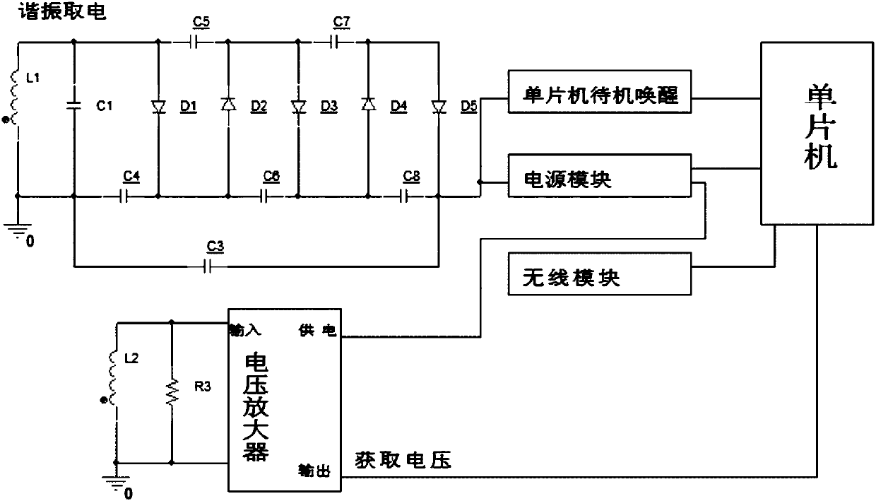
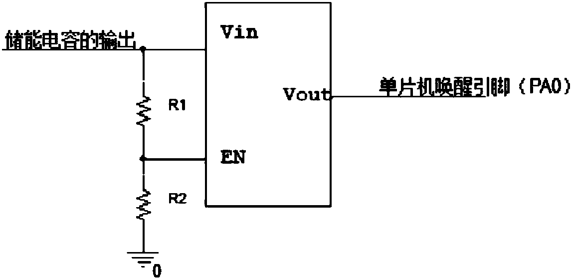
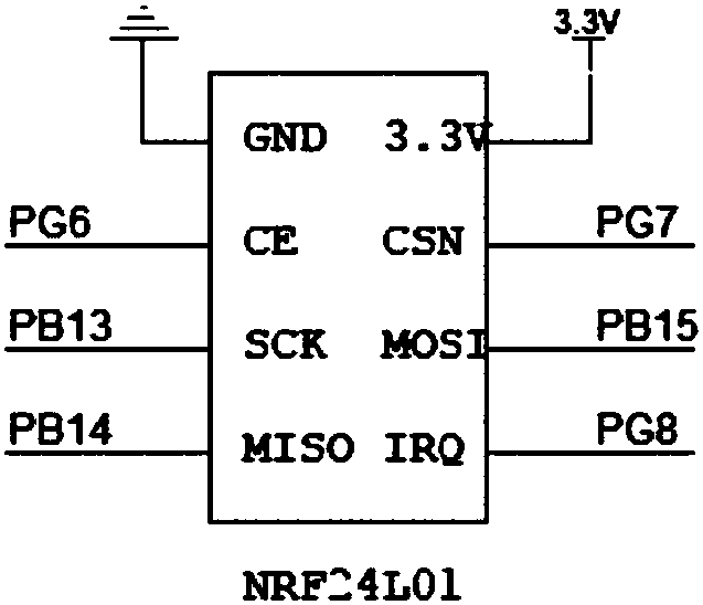
[0022] like figure 1 As shown, a passive wireless current sensor includes a resonant power-taking module, a voltage-obtaining module, a single-chip standby wake-up module, a wireless module, a power supply module and a single-chip microcomputer, and the output of the resonant power-taking module is connected to the single-chip standby wake-up module and the power supply module. The single-chip computer standby wake-up module, the wireless module and the voltage acquisition module are all connected to the single-chip computer, and the power supply module is connected to the single-chip computer and the voltage acquisition module;

[0023] The resonant power-taking module includes a first current transformer L1, a resonant capacitor C1, an energy storage ca...


PUM


Abstract

The invention discloses a passive and wireless current sensor device. By means of resonant electric energy acquisition technology, electric energy acquisition efficiency is improved, furthermore a capacitor is charged through a rectifying and voltage doubling circuit. After enough amount of electric energy is acquired, a single-chip microcomputer in a standby state is waken up. The single-chip microcomputer converts voltage which is acquired by another mutual inductor circuit to a current value of a cable. Furthermore the single-chip microcomputer transmits the data to outside by means of a wireless transmission module. The passive and wireless current sensor device has advantages of realizing no requirement for power supplying by an external power supply, setting a cable current monitoring problem, preventing high-voltage electric shock, and effectively reducing power supplying cost and maintenance cost.

Description

technical field [0001] The invention relates to the technical field of power electronics, in particular to a passive wireless current sensor device. Background technique [0002] On-line real-time monitoring of transmission cables is not only of great significance to the safety and stability of power systems, but also a necessary condition for the development of smart grids. Manual detection methods are not only time-consuming and laborious, but also lack real-time performance and may bring potential dangers. At present, although there are automatic detection equipment distributed on cables, the power supply for a large number of automatic detection equipment is not easy to obtain, and the reliability of the equipment cannot be guaranteed. Contents of the invention [0003] Aiming at the technical problems existing in the prior art, the present invention provides a passive wireless current sensor device, which uses a resonant power-taking circuit to generate induced electr...

Claims


Application Information

Patent Timeline
Patent Type & Authority Applications(China)
IPC IPC(8): G01R15/16G01R15/18G01R15/20G05F1/46G05B19/042
CPCG05B19/042G05F1/461G01R15/16G01R15/18G01R15/20G05B2219/25359Y02D30/70
Inventor 陈浩赵裕昊滕国龙吴建德
Owner ZHEJIANG UNIV
Learn More