Mine bucket tooth

A mining and bucket tooth seat technology, applied in the field of mining bucket teeth, can solve the problems affecting the service life of mining bucket teeth, low hardness and strength, etc., to improve the service life and use efficiency, high fastness, and easy to use. Effect

Inactive Publication Date: 2018-02-02
ZHEJIANG PACIFIC MACHINERY CO LTD
View PDF11 Cites 1 Cited by
  • Summary
  • Abstract
  • Description
  • Claims
  • Application Information

AI Technical Summary

Problems solved by technology

Because the cemented carbide cutter head of the mining bucket tooth plays a role in coal mining, it has good wear resistance, so it can play a certain wear-resistant mining effect and improve the service life of the bucket tooth; but as a mining bucket tooth product, In the specific mining process, the entire bucket tooth extends into the coal mine seam, and the head carbide cutter head plays a role of forward rotation and propulsion. The entire bucket tooth body, especially close to and installed the cemented carbide The front end of the bucket tooth body of the cutter head is also more or less strongly rubbed by the ore layer. Since the bucket tooth body is generally made of medium-carbon high-strength alloy steel after quenching and tempering treatment, its hardness and strength are much lower than those of the head The inlaid carbide cutter head causes the bucket teeth to wear first during the working process, thus affecting the service life of the entire mining bucket teeth

Method used


Image

  • Mine bucket tooth
  • Mine bucket tooth
  • Mine bucket tooth

Examples


Embodiment Construction

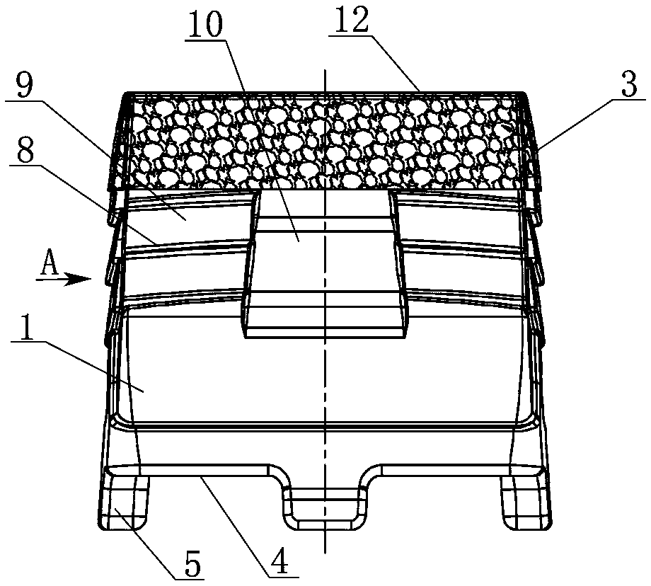
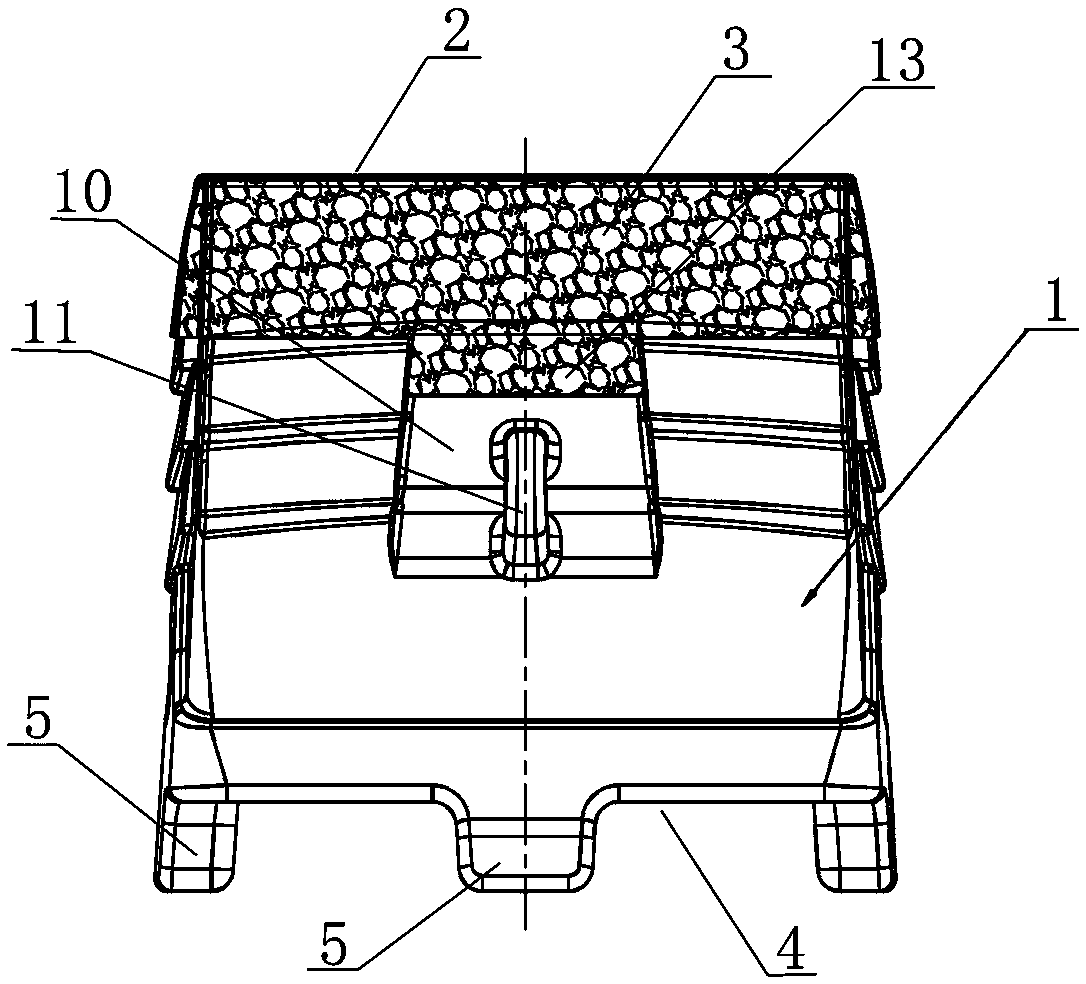
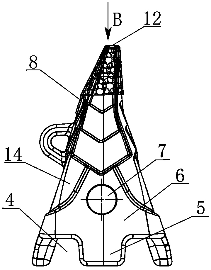
[0013] The present invention will be described in detail below in conjunction with accompanying drawing: Figure 1-4 As shown, a mining bucket tooth according to the present invention includes a hollow triangular conical sleeve 1 for socketing the bucket tooth seat, and the conical tip 2 of the triangular conical sleeve 1 Surrounding the granular hard alloy welding layer 3 formed by overlay welding, the four bottom edges 4 of the triangular conical sleeve body 1 are respectively connected with an outwardly protruding plug-in block 5 located in the middle of each bottom edge; The triangular symmetrical sides 6 of the tapered sleeve 1 are respectively provided with positioning through holes 7 for fixing the tooth holder.

[0014] As shown in the figure, at least two protruding stepped ring surfaces 8 are provided on the upper outer wall surface of the triangular conical casing 1, at the middle position of the front and rear tapered surfaces 9 of the triangular conical casing 1, ...


PUM


Abstract

Disclosed is a mine bucket tooth. The mine bucket tooth comprises a hollow triangular conic sleeve body used for being connected with a bucket tooth base in a sleeving mode. A granular cemented carbide welding layer formed by welding building up is surrounded by the whole cone tip head part of the triangular conic sleeve body. External convex inserting and connecting blocks located in the middle of each bottom edge are correspondingly connected with the four bottom edges of the triangular conic sleeve body. Positioning through holes used for fixing the bucket tooth base are formed in the triangular symmetrical side edges of the triangular conic sleeve body correspondingly. The upper outer wall surface of the triangular conic sleeve body is provided with at least two outer convex stepped toruses. The middles of the front and back conical surfaces of the triangular conic sleeve body as well as the lower portion of the granular cemented carbide welding layer located on the stepped torusesare provided with raised square blocks. The raised square block on one side is connected with a sleeve ring arranged vertically. The cone tip head part of the triangular conic sleeve body is a narrowlong-strip end face provided with the granular cemented carbide welding layer in a covered mode. The mine bucket tooth has the characteristics that the structure is simple and reasonable, using is convenient, the wear resistance of the product surface can be increased, the strength is high, the fastness is high, and the product service life and use efficiency can be improved.

Description

technical field [0001] The invention relates to a mining bucket tooth, which is installed on a coal mine excavation machine and used for cutting coal and rock, and belongs to the technical field of coal mine excavation machinery engineering. Background technique [0002] Mining bucket teeth are one of the vulnerable parts in coal mining and tunneling machinery, and are the main tool for coal falling and crushing. Its performance directly affects the production capacity, power consumption, and stable operation of coal mining machinery. and the service life of other related components. [0003] The existing mining bucket teeth are mainly composed of a bucket tooth body and a hard alloy cutter head. The cemented carbide cutter head is embedded in a concave hole at the head end of the bucket tooth body and is fixedly connected by brazing. Because the cemented carbide cutter head of the mining bucket tooth plays a role in coal mining, it has good wear resistance, so it can play ...

Claims


Application Information

Patent Timeline
IPC IPC(8): E21C35/183
CPCE21C35/183E21C35/1837
Inventor 周志建
Owner ZHEJIANG PACIFIC MACHINERY CO LTD
Why Eureka
Try Eureka