


Quick Research
Generate reliable direction feasibility study reports for your R&D in just a few steps.

Technical Q&A
Discover and master advanced knowledge NOW. Basics, ideas, possibilities, all at once.

Find Solutions
As an expert in R&D theories, this can generate solutions to your technical problems instantly.

Evaluate Feasibility
Analyze your overall solution with one click, know your potential R&D risks in advance.

Monitor Landscape
Get weekly tech updates, stay abreast of the latest tech innovations and key insights.
A kind of transmission method and device of uplink reference signal
A technology for a reference signal and a transmission method, applied in the field of uplink reference signal transmission methods and devices, can solve the problems of partial interference of reference measurement signal data, destruction of uplink measurement reference signal time domain orthogonality, lack of beam detection, etc. The effect of data transmission accuracy
- Summary
- Abstract
- Description
- Claims
- Application Information
AI Technical Summary
Problems solved by technology
Method used
Image

Examples
Embodiment 1
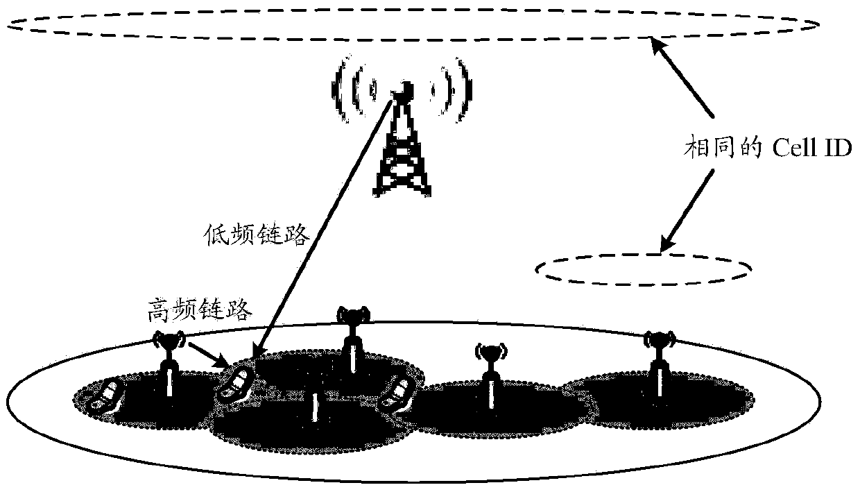
[0112] Such as Figure 8 As shown, the first embodiment provides an application figure 2 The shown high-frequency micro-site and low-frequency macro-site hybrid networking or Figure 7 The shown frame structure in a communication system in which multiple high-frequency base stations are mixed and networked. Among them, the high-frequency base station in the mixed networking scenario of multiple high-frequency base stations may be a high-frequency micro station or a high-frequency macro station.
[0113] Figure 8 In, 10 milliseconds is used as the frame length of a radio frame; the radio frame is composed of 10 radio subframes with a frame length of 1 millisecond; and a radio subframe is divided into 8 radio subframes with a length of 0.125 milliseconds. The time slot (time slot); where each time slot is composed of Q symbols, which can be single-carrier symbols or multi-carrier symbols, such as OFDM symbols. A typical Q value can be set to 7n, where n is a positive integer. Th...
Embodiment 2
[0116] Such as Figure 9A with Figure 9B As shown, the second embodiment gives another application figure 2 The shown high-frequency micro-site and low-frequency macro-site hybrid networking or Figure 7 The shown frame structure in a communication system in which multiple high-frequency base stations are mixed and networked. Among them, the high-frequency base station in the mixed networking scenario of multiple high-frequency base stations may be a high-frequency micro station or a high-frequency macro station.
[0117] Such as Figure 9A As shown, the difference from the first embodiment is that since the uplink reference signal is not continuous in time domain resources, the NoMP interval for transmitting the uplink reference signal is also distributed, and the NoMP interval is divided into several NoMP segments.
[0118] Figure 9B In, 10 milliseconds is used as the frame length of a radio frame; the radio frame is composed of 10 radio subframes with a frame length of 1 milli...
Embodiment 3
[0121] Based on the frame structures given in the first and second embodiments, the third embodiment provides a method for transmitting uplink synchronization reference signals, which is applied to figure 2 The network deployment scenario shown, such as Picture 10 As shown, the specific steps include:
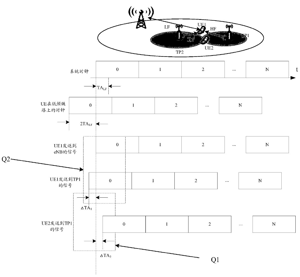
[0122] Step 101: The terminal completes synchronization with the low-frequency macro station based on the low-frequency link, and obtains the system clock on the network side and the terminal's uplink TA on the low-frequency link.
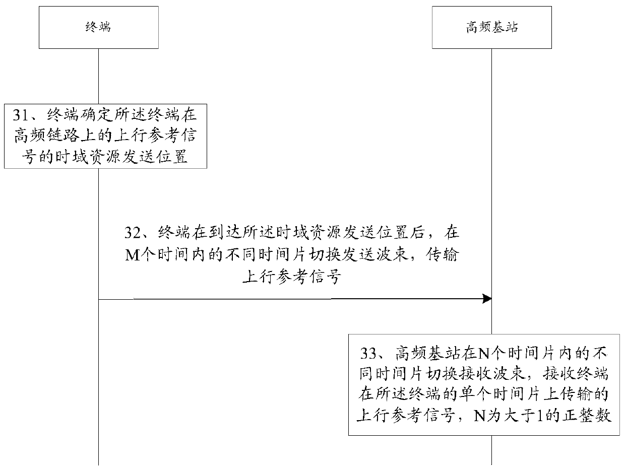
[0123] Step 102: The terminal determines the sending position of the time domain resource of its own uplink synchronization reference signal on the high frequency link.
[0124] The method for determining the sending position of time domain resources can use the system clock obtained by the low-frequency link and / or the uplink TA value obtained by the terminal on the low-frequency link, and the starting point of a certain time slot of the low-frequency li...
PUM
 Abstract
Description
Claims
Application Information
 - R&D Engineer
- R&D Manager
- IP Professional
- Industry Leading Data Capabilities
- Powerful AI technology
- Patent DNA Extraction
Browse by: Latest US Patents, China's latest patents, Technical Efficacy Thesaurus, Application Domain, Technology Topic, Popular Technical Reports.
© 2024 PatSnap. All rights reserved.Legal|Privacy policy|Modern Slavery Act Transparency Statement|Sitemap|About US| Contact US: help@patsnap.com