Cutting clamp applicable to clamping workpiece at multiple angles

A technology of angle clamping and workpiece, which is applied in the direction of manufacturing tools, metal processing machinery parts, clamping, etc., can solve the problems of affecting workpiece processing, reducing work efficiency, and applying large force, so as to improve the coefficient of friction, improve efficiency, and improve The effect of clamping force

Pending Publication Date: 2018-01-30
彭州市和顺电器有限公司
View PDF0 Cites 3 Cited by
  • Summary
  • Abstract
  • Description
  • Claims
  • Application Information

AI Technical Summary

Problems solved by technology

[0003] Since the movable block can rotate when clamping the workpiece, the angle of the movable block needs to be adjusted after clamping the workpiece each time to facilitate the next clamping of the workpiece, which reduces the work efficiency when operating in small batches and large batches; the general cutting machine The clamping working surface of the clamping device is two parallel planes. When clamping the rod-shaped workpiece, the rod-shaped workpiece is in two-line contact with the two clamping surfaces. It is necessary to apply a large clamping force to clamp the workpiece, but at the same time Large clamping force will cause obvious indentation at the two line contact positions, which will affect the subsequent processing of the workpiece

Method used


Image

  • Cutting clamp applicable to clamping workpiece at multiple angles
  • Cutting clamp applicable to clamping workpiece at multiple angles

Examples


Embodiment Construction

[0024] The technical solution of the present invention will be further described in detail below in conjunction with the accompanying drawings, but the protection scope of the present invention is not limited to the following description.

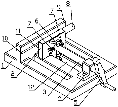
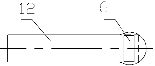
[0025] Such as figure 1 As shown, a fixture suitable for clamping a workpiece 8 at various angles, including a base 1, a movable block 2, a screw rod 3, a latch 6, a support seat 4, a support seat 4 and a fixed block 9 respectively fixed at both ends of the base 1 , the screw mandrel 3 is arranged along the vertical direction of the clamping working surface of the fixed block 9 and cooperates with the internal thread provided in the support seat 4. Gap fit, the movable block 2 is located between the support seat 4 and the fixed block 9; it also includes two elastic parts 7, the elastic parts 7 are symmetrically arranged on both sides of the head end of the screw mandrel 3, and the two ends of the elastic part 7 are respectively connected wi...


PUM


Abstract

The invention discloses a cutting clamp applicable to clamping a workpiece at multiple angles. The cutting clamp comprises a base, a movable block, a screw rod, a plug pin, a supporting base and a fixed block, the supporting base and the fixed block are fixedly connected to the two ends of the base respectively, the screw rod is perpendicular to the clamping working surface of the fixed block andis matched with an inner thread arranged in the supporting base, the head end of the screw rod is hinged to the movable block through the upper end of the plug pin, the movable block is in clearance fit with the plug pin, is located between the supporting base and the fixed block and further comprises two elastic parts, the elastic parts are symmetrically arranged at the two sides of the head endof the screw rod, and the two ends of each elastic parts are connected with the movable block and the screw rod respectively. By arranging the elastic parts, after the movable block rotates for some angle to clamp the workpiece, the movable block can automatically return to the position parallel to the fixed block, and the efficiency of continuous work is improved; meanwhile, by arranging cross net patterns and an arc groove, the clamping force among the clamping surfaces is improved, and the reliability is high.

Description

technical field [0001] The invention relates to a clamp used on a cutting machine, in particular to a cutting clamp suitable for clamping workpieces at various angles. Background technique [0002] Cutting machine is widely used in construction, hardware, petrochemical, mechanical metallurgy and hydropower installation and other fields. The cutting machine can cut metal square flat pipe, square flat steel, I-beam, channel steel, carbon steel, round pipe, bar, etc. It has a wide range of applications. [0003] Since the movable block can rotate when clamping the workpiece, the angle of the movable block needs to be adjusted after clamping the workpiece each time to facilitate the next clamping of the workpiece, which reduces the work efficiency when operating in small batches and large batches; the general cutting machine The clamping working surface of the clamping device is two parallel planes. When clamping the rod-shaped workpiece, the rod-shaped workpiece is in two-line...

Claims


Application Information

Patent Timeline
Patent Type & Authority Applications(China)
IPC IPC(8): B23Q3/06
Inventor 向秀敏
Owner 彭州市和顺电器有限公司
Why Eureka
Try Eureka