
Cylindrical battery cell module

A cell module and cylinder technology, applied in the field of cylindrical cell modules, can solve the problems of no permanent positive and negative marks, connection strength and structural influence, no positive and negative bus plate, etc., to improve insulation and short circuit protection performance , reliable connection and convenient wiring

Pending Publication Date: 2018-01-26
BEIJING PRIDE NEW ENERGY BATTERY
View PDF8 Cites 5 Cited by
  • Summary
  • Abstract
  • Description
  • Claims
  • Application Information

AI Technical Summary

Problems solved by technology

These two connection methods are not designed with a buffer. During use, the connection strength and structure will be affected due to vibration and thermal expansion and contraction, which will cause the connection resistance to increase and cause the temperature of the connection to rise. A series of security and reliability issues
There is no positive and negative bus plate insulation protection in the traditional cylindrical module, which is easy to cause short circuit during handling and storage
There is no permanent and obvious positive and negative pole marking in the traditional cylindrical module, and it is easy to cause the positive and negative poles to be wrongly connected during use
When the traditional cylindrical cell module is composed of multiple strings, there is no anti-error feature for reverse polarity

Method used


Image

  • Cylindrical battery cell module
  • Cylindrical battery cell module
  • Cylindrical battery cell module

Examples


Embodiment Construction

[0043] The principles and features of the present invention are described below in conjunction with the accompanying drawings, and the examples given are only used to explain the present invention, and are not intended to limit the scope of the present invention.

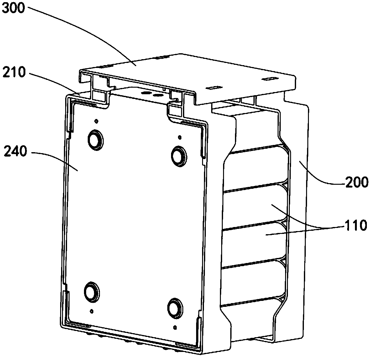
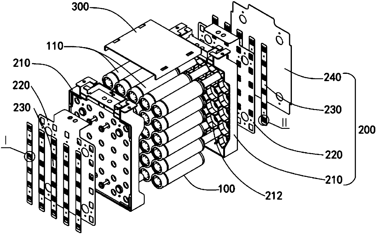
[0044] Such as Figure 1 to Figure 10 As shown, the present invention relates to a cylindrical cell module, including a battery pack 100 formed by combining a plurality of cylindrical cells 110 arranged in an array, two electrode assemblies 200 and a top cover 300;

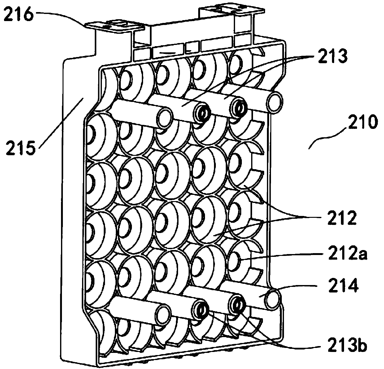
[0045]The two electrode assemblies 200 are arranged relatively in parallel, and are respectively located at the positive end and the negative end of the battery pack 100 . The electrode assembly 200 is provided with a plurality of cell fixing grooves 212 on the side close to the battery pack 100 . Both the positive terminal and the negative terminal of the cylindrical battery cell 110 are located in the battery cell fixing groove 212, and the two electr...


PUM


Abstract

The invention relates to a cylindrical battery cell module. The cylindrical battery cell module comprises a battery pack formed by combining a plurality of cylindrical battery cells arranged in an array manner, two electrode assemblies and a top cover; the two electrode assemblies are arranged in parallel, and are respectively positioned at the positive electrode end and the negative electrode endof the battery pack, a plurality of battery cell fixing grooves are arranged at one side, close to the battery pack, of every electrode assembly, the positive electrode ends and the negative electrode ends of the cylindrical battery cells are positioned in the battery cell fixing grooves, and the two electrode assemblies are fixedly connected through a connecting piece; and two sides of the top cover are respectively connected with the two electrode assemblies. The plurality of small-capacity cylindrical battery cells are connected in parallel to form the large-capacity battery pack, and thebattery pack is wrapped with the two electrode assemblies to form the cylindrical battery cell module, so the cylindrical battery cell module has the advantages of simple structure, safety and reliability in connection, good protection, short development period, and meeting of the large-capacity requirements of electric automobiles; and a plurality of cylindrical battery cell modules can be connected in a mutual insertion manner to form a module group having the advantages of difficulty in making mistakes of connection, convenience in routing, reliability in connection, and good resistance toshock and impact.

Description

technical field [0001] The invention relates to the field of automobile energy, in particular to a cylindrical cell module. Background technique [0002] At present, the global automobile industry is facing the huge challenge of energy and environmental issues; pure electric vehicles with high energy utilization rate and no pollution to the environment are increasingly becoming the development direction of the future automobile industry. As the core component of a pure electric vehicle, the performance of a power battery will directly affect the performance of a pure electric vehicle. In order to meet the cruising range of electric vehicles, the power battery system is required to have a large capacity, so it is necessary to connect multiple small-capacity cylindrical lithium-ion batteries in parallel to form a large-capacity battery module. Most of the traditional modules connect the connecting piece and the battery together by bolts, or weld the connecting piece and the b...

Claims


Application Information

Patent Timeline
IPC IPC(8): H01M2/20H01M2/10H01M50/213H01M50/249H01M50/502
CPCY02E60/10
Inventor 袁格年赵孟黄伟郭小冬盛力
Owner BEIJING PRIDE NEW ENERGY BATTERY
Learn More