Rubber ball collecting equipment

A technology of equipment and rubber balls, which is applied in the field of condenser cooling and pipe cleaning equipment, can solve the problems of obstructing the discharge of balls, long ball discharge paths, and large water resistance, and achieves the effect of not easy to block and high efficiency of ball collection.

Pending Publication Date: 2018-01-23
TIANJIN HUADIAN BEICHEN DISTRIBUTED ENERGY
View PDF8 Cites 2 Cited by
  • Summary
  • Abstract
  • Description
  • Claims
  • Application Information

AI Technical Summary

Problems solved by technology

[0004] However, the structure of the traditional rubber ball collection net often adopts "positive V" and "cone". These two forms have relatively large water resistance, and the direction of the ball is perpendicular to the direction of the water flow. It is easy to form a dead zone at the ball outlet. 1. Impurities in the circulating water are easy to accumulate at the ball outlet, hindering the ball, and the ball outlet path is long. When the ball collection net is arranged horizontally, the conical structure is difficult to form an effective flow field and other disadvantages

Method used


Image

  • Rubber ball collecting equipment
  • Rubber ball collecting equipment
  • Rubber ball collecting equipment

Examples


Embodiment 1

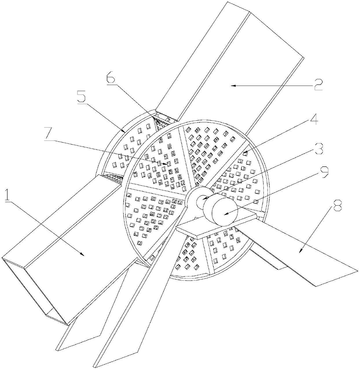
[0033] Example 1, the end of the rotating shaft 3 is connected to the motor 9, the rotating blade 6 is made of flexible hollow grid material, the motor 9 drives the rotating shaft 3 to rotate, the water flows down from the gap of the rotating blade 6, and then the rubber ball is trapped in the grid space, the grid space The outlet of the rubber ball is rotated to the nozzle of the slanted downward goal tube 1, and the rubber ball enters along the trend, thereby realizing the ball collection operation.

Embodiment 2

[0034] Embodiment 2, the rotating blade 6 is configured as a flexible mesh, and the connecting blade 7 is configured as a hollow mesh. The rotating blade 6 has no water leakage function, because the outlet of the ball tube 2 is set obliquely downward, so under the impact of the water flow and the rubber ball, the rotating blade 6 will rotate, thereby driving the rotating shaft 3 to rotate, and then driving the entire mechanism to rotate , and in the process of rotation, because the connecting blade 7 is hollowed out, the water flows downstream under the action of gravity, while the rubber ball is trapped, and when it rotates to the nozzle of the goal tube 1, it is thrown off the inlet and outlet tube , and then complete the ball collection operation.

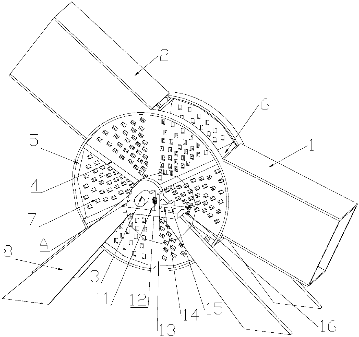
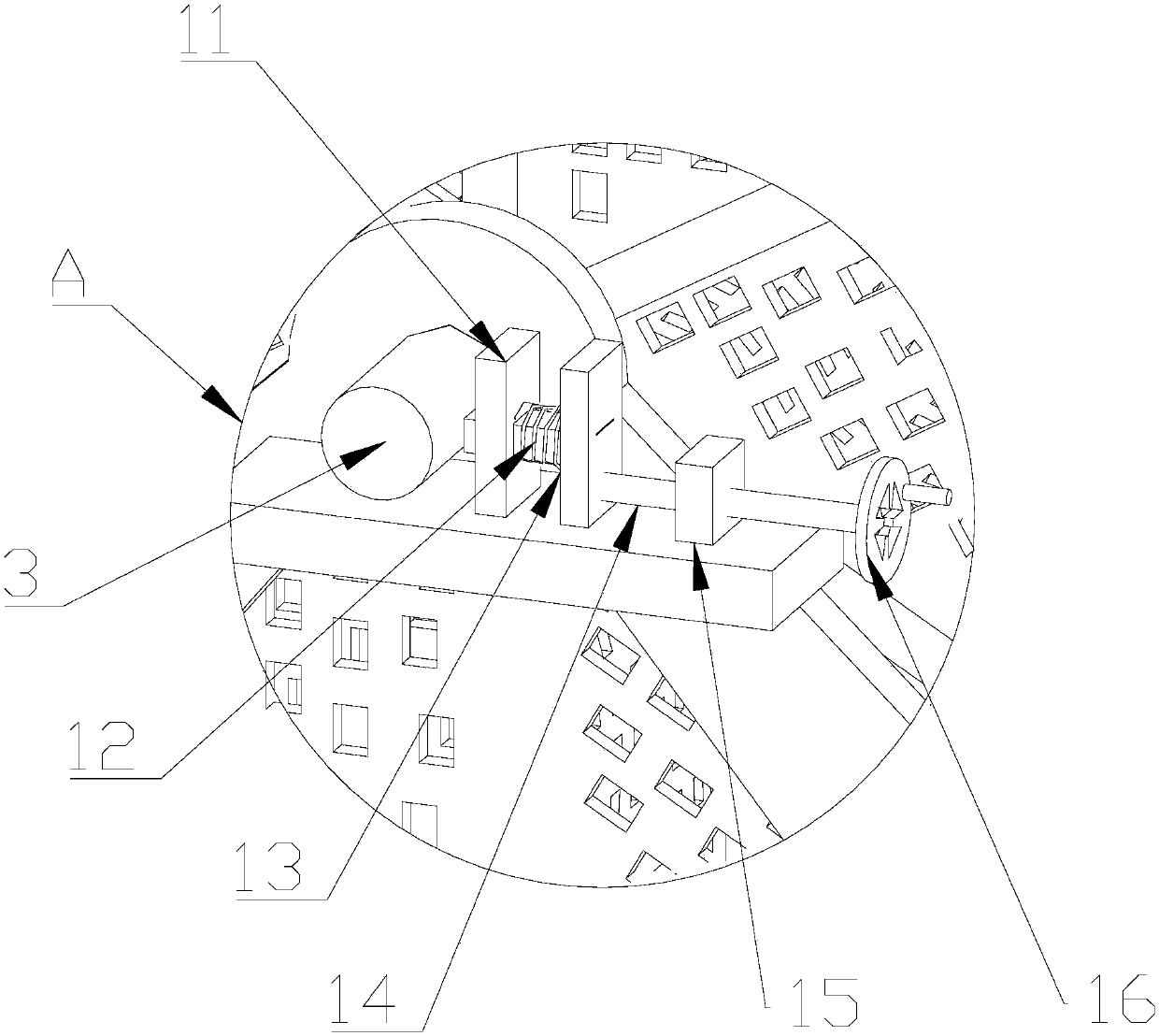
[0035] When the water potential flowing out from the outlet pipe 3 is constant, when the rotating speed of the rotating shaft 3 needs to be adjusted, the rotating speed can be slowed down so that the screw 14 can be moved toward...


PUM


Abstract

The invention provides rubber ball collecting equipment. The rubber ball collecting equipment comprises a rotating ball collecting unit, a ball feeding pipe and a ball discharging pipe, wherein the rotating ball collecting unit comprises a rotating shaft; two groups of support keels in circular patterns are arranged on the rotating shaft at a certain interval in a symmetric manner; the tail ends of each group of support keels are connected with a rotating wheel; rotating blades are connected between the symmetric keels; arc-shaped connecting blades are connected between every two adjacent keels; the ball feeding pipe is arranged at the inclined upper part of the rotating ball collecting unit; the ball discharging pipe is arranged at the inclined lower part of the rotating ball collecting unit; the two ends of the rotating shaft are connected with a bracket through bearings; and a rotating speed regulating mechanism is arranged at the tail end at one end of the rotating shaft. Accordingto the rubber ball collecting equipment provided by the invention, the following effects are achieved: the ball discharging direction is different from the water flowing direction, the ball discharging speed is regulatable, and the ball collecting efficiency is high.

Description

technical field [0001] The invention belongs to the field of cleaning equipment for cooling tubes of condensers, and in particular relates to a device for collecting rubber balls. Background technique [0002] The rubber ball cleaning device is the best equipment for effectively cleaning the cooling pipe of the condenser during the operation of the steam turbine unit. The performance of the device directly affects the cleaning degree and heat transfer effect of the steam turbine condenser. [0003] The ball collecting device is one of the key components in the process of cleaning the rubber balls in the condenser. To maintain the continuous cleaning of the condenser tube by the sponge rubber balls, the rubber balls must be continuously fed into the cleaning system. Then take back the rubber ball that has cleaned the cooling pipe in time, and use it to clean the pipe again. The ball collecting device is used to collect all the rubber balls dispersed in the cooling water fo...

Claims


Application Information

Patent Timeline
Patent Type & Authority Applications(China)
IPC IPC(8): F28G1/12
CPCY02W30/62
Inventor 常广永
Owner TIANJIN HUADIAN BEICHEN DISTRIBUTED ENERGY
Why Eureka
Try Eureka