Full-automatic reinforcing-steel-bar feeding machine with fixed-length feeding function

A fully automatic, fixed-length technology, applied in the field of fully automatic steel bar feeder, can solve the problems of inaccurate fixed-length feeding, uncontinuous feeding, unreliable clamping, etc., to achieve accurate length, high working stability, and feeding efficiency consistent effect

Active Publication Date: 2018-01-23
CHINA METALLURGICAL CONSTR ENG GRP
View PDF6 Cites 0 Cited by
  • Summary
  • Abstract
  • Description
  • Claims
  • Application Information

AI Technical Summary

Problems solved by technology

[0004] Aiming at the above-mentioned deficiencies of the prior art, the technical problem to be solved by the present invention is to provide a fully automatic steel bar feeder capable of feeding material at a fixed length, so as to avoid unreliable clamping of steel bars caused by unstable rollers, unable to continuously feed materials, and unable to precisely Fixed-length feeding problem, to achieve effective clamping of steel bars, good feeding continuity, convenient operation, and accurate output of steel bar length

Method used


Image

  • Full-automatic reinforcing-steel-bar feeding machine with fixed-length feeding function
  • Full-automatic reinforcing-steel-bar feeding machine with fixed-length feeding function
  • Full-automatic reinforcing-steel-bar feeding machine with fixed-length feeding function

Examples


Embodiment Construction

[0051] The specific implementation manners of the present invention will be further described in detail below in conjunction with the accompanying drawings.

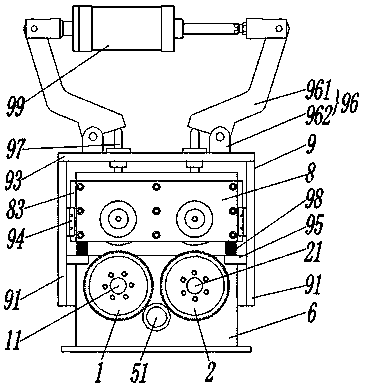
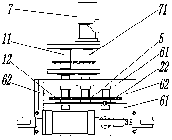
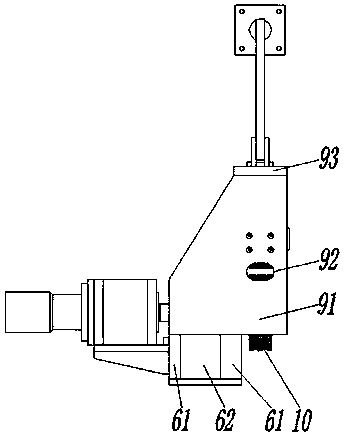
[0052] see Figure 1~6 , a fully automatic steel bar feeder capable of feeding at a fixed length, including a first driven wheel 3 and a first driving wheel 1 arranged up and down on the same vertical plane, and the first driving wheel 1 is arranged on a first rotating shaft 11, so The first rotating shaft 11 is rotatably coupled to the frame body 6, and the first rotating shaft 11 is connected to the hydraulic motor 7 to input torque; it also includes a vertical plane located in the vertical plane where the first driven wheel 3 and the first driving wheel 1 are located and paired up and down. The second driven wheel 4 and the second driving wheel 2 are provided; the second driving wheel 2 is arranged on the second rotating shaft 21 , and the second rotating shaft 21 is rotatably coupled to the frame body 6 .

[0053] T...


PUM


Abstract

The invention relates to a full-automatic reinforcing-steel-bar feeding machine with the fixed-length feeding function. The full-automatic reinforcing-steel-bar feeding machine with the fixed-length feeding function comprises a first driven wheel, a first driving wheel, a second driven wheel and a second driving wheel, wherein the first driven wheel and the first driving wheel are arranged in a paired mode up and down and arranged on the same vertical face, and the second driven wheel and the second driving wheel are arranged in a paired mode up and down and arranged on the same vertical face;the first driven wheel and the second driven wheel are arranged in a lifting frame and are equal in height; the lifting frame comprises two lifting plates, wherein the first driven wheel and the second driven wheel are rotatably connected between the two lifting plates; the full-automatic reinforcing-steel-bar feeding machine also comprises a lifting driving device, wherein sliding grooves are formed in the lifting driving device, and sliding rails matched with the sliding grooves are arranged on the lifting frame and can move along the sliding grooves under the effect of the lifting drivingdevice; a hydraulic motor is connected to the first driving wheel and connected with a hydraulic control valve; an encoder is connected to the second driven wheel, and the hydraulic control valve andthe encoder are connected with a PLC. According to the full-automatic reinforcing-steel-bar feeding machine with the fixed-length feeding function, the rolling wheels are stable, clamping of reinforcing steel bars is reliable, feeding can be effectively and continuously carried out, the feeding lengths of the reinforcing steel bars are effectively controlled through an electric control part, the output feeding lengths of the reinforcing steel bars are accurate, the automatic degree is high, and operating is convenient.

Description

technical field [0001] The invention belongs to the technical field of wire feeding in wire processing machinery or equipment, and in particular relates to a fully automatic steel bar feeding machine capable of feeding materials at a fixed length. Background technique [0002] The steel bar is usually supplied in a disc shape. In actual use, the disc-shaped steel bar needs to be straightened and cut, and then bent into the desired shape before it can be used. Therefore, it is necessary to pull out the steel bar first, and then perform subsequent functions. With the development of industry, a device that is easy to operate and can continuously send steel bars has emerged. The principle is basically to clamp the steel bar between two rollers, and then realize the feeding through the rotation of the rollers. Such a steel bar feeding device is in Some problems have also been exposed in actual use: 1. The vibration during the feeding process or the reaction of the clamping force ...

Claims


Application Information

Patent Timeline
Patent Type & Authority Applications(China)
IPC IPC(8): B21F23/00
Inventor 李智能刘赫凯杨炬蒋玉富陈刚
Owner CHINA METALLURGICAL CONSTR ENG GRP
Why Eureka
Try Eureka