Air supply device and method for catching insects
An air supply device and blower technology, applied in the direction of separation methods, chemical instruments and methods, devices for catching or killing insects, etc., can solve the problems that the attracting light cannot fully reach and the performance of insect catching is reduced, so as to improve the performance of catching insects and reduce the insects. Adverse effects, the effect of improving the insect-catching effect
- Summary
- Abstract
- Description
- Claims
- Application Information
AI Technical Summary
Problems solved by technology
Method used
Image
Examples
no. 1 Embodiment approach
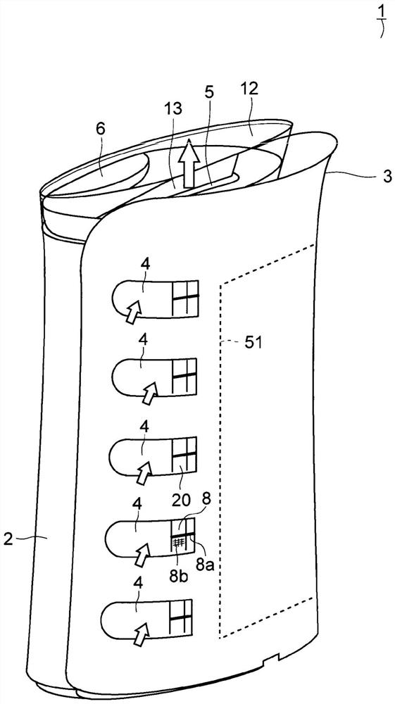
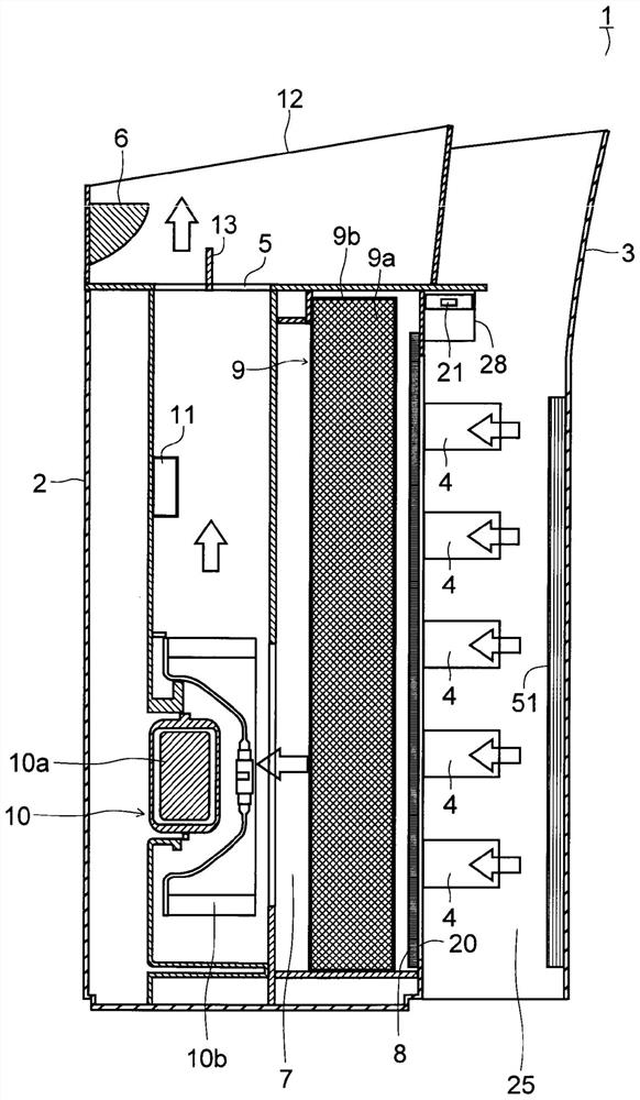
[0039] Hereinafter, embodiments of the present invention will be described with reference to the drawings. figure 1 and figure 2 A perspective view and a side cross-sectional view of the blower device according to the first embodiment are respectively shown. in addition, figure 1 and figure 2 In , hollow arrows indicate air flow. The air blower 1 has a casing 2 that is placed on a floor or the like in a living room and has a substantially elliptical horizontal cross-sectional shape. A detachable cover member 3 is attached to the back side of the housing 2, and an insect trap sheet 51, which will be described in detail later, is disposed inside the cover member 3. As shown in FIG. The front surface of the casing 2, the back surface of the casing 2, and the outer surface of the cover member 3 are formed in black.
[0040] A sleeve portion 12 made of transparent resin is provided at an edge portion of the upper surface of the housing 2 . An operation unit 6 is provided on...
no. 2 Embodiment approach
[0121] Next, a second embodiment of the present invention will be described. In this embodiment, it is different from the first embodiment in that an insect-killing sheet is provided instead of the insect-catching sheet 51 . Other parts are the same as those of the first embodiment.
[0122] An insect-killing sheet (not shown) is attached to the mounting plate 55 instead of the insect-catching sheet 51 . The pest control sheet is formed, for example, by coating a volatile insecticide on a base sheet (not shown). Thus, the deinsectization component can be made in the insect trapping space 25 (refer to figure 2 ) in the air to diffuse and kill insects, thereby trapping insects in the insect trapping space 25. In addition, at this time, if a detachable tray or the like is provided under the insect trapping space 25, the insects that have been eliminated and fallen in the insect trapping space 25 can be collected and discarded easily, so it is preferable.
no. 3 Embodiment approach
[0124] Next, a third embodiment of the present invention will be described. In this embodiment, it is different from the first embodiment in that a spray unit is provided instead of the insect trap sheet 51 . Other parts are the same as those of the first embodiment.
[0125] A spray unit (not shown) is provided on the inner upper portion of the cover member 3 . Spray portion has the tank body (not shown) that is filled with insecticide, to insect trap space 25 (referring to figure 2 ) spray insecticide. Thereby, the insects in the insect-trapping space 25 can be exterminated, and the insects can be caught in the insect-trapping space 25 . For example, the spray unit may spray the insecticide after a predetermined time elapses after the operation of the air blower 1 has elapsed, or may spray the insecticide by operating the operation unit 6 . In addition, since the spray part 60 should just spray insecticide in the insect trap space 25, instead of the cover member 3, the ...
PUM
| Property | Measurement | Unit |
|---|---|---|
| recovery rate | aaaaa | aaaaa |
Abstract
Description
Claims
Application Information
 - R&D
- Intellectual Property
- Life Sciences
- Materials
- Tech Scout
- Unparalleled Data Quality
- Higher Quality Content
- 60% Fewer Hallucinations
Browse by: Latest US Patents, China's latest patents, Technical Efficacy Thesaurus, Application Domain, Technology Topic, Popular Technical Reports.
© 2025 PatSnap. All rights reserved.Legal|Privacy policy|Modern Slavery Act Transparency Statement|Sitemap|About US| Contact US: help@patsnap.com


