Flood prevention structure

A technology of flood control board and locking mechanism, which is applied in the direction of breakwater, coastline protection, jetty, etc., and can solve the problems of large storage space, non-reusable use, and environmental pollution

Pending Publication Date: 2018-01-19
中铝南铝(福建)铝结构技术开发有限公司
View PDF5 Cites 0 Cited by
  • Summary
  • Abstract
  • Description
  • Claims
  • Application Information

AI Technical Summary

Problems solved by technology

Sandbags require a lot of manpower to fill sand or soil, and when the flood subsides, it takes a lot of manpower to remove sand or soil from the sandbags, and the final sandbags are basically broken, cannot be reused, and pollute the environment , the effect of flood control and flood fighting is poor, and it is easy to be washed away when the flood is large; the storage space occupies a large area and pollutes the space environment

Method used


Image

  • Flood prevention structure
  • Flood prevention structure
  • Flood prevention structure

Examples


Embodiment 1

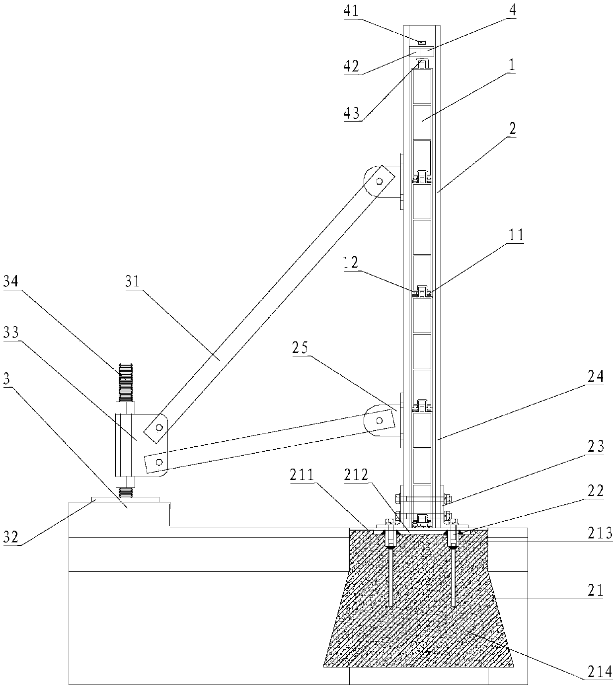
[0044] Please refer to figure 1 with figure 2 , Embodiment 1 of the present invention is:

[0045] A flood control structure, comprising a flood control plate 1, a column 2 and a support frame 3, the flood control plate 1 is sandwiched between adjacent columns 2, and the support frame 3 is connected to the side of the column 2 to provide support for the column 2;

[0046] The lower end of the flood control board 1 is a groove, and the upper end is a protrusion matching the lower end groove, and multiple flood control boards 1 are vertically inserted between adjacent columns 2;

[0047] The column 2 includes an embedded part 21, a bolt, a center column base 23, a center column 24 and a first trunnion support 25; 23 is fixedly connected, the center column 24 is fixed in the center column base 23, and the first trunnion support 25 is bolted on the center column 24.

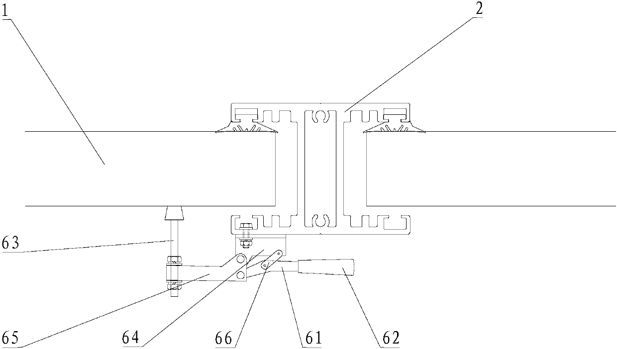
[0048] The flood control plate 1 also includes a first sealing rubber strip 11; the first T-shaped groove 12 f...

Embodiment 2

[0055] Please refer to figure 1 with image 3 , the second embodiment of the present invention is:

[0056] A flood control structure, comprising a flood control plate 1, a column 2 and a support frame 3, the flood control plate 1 is sandwiched between adjacent columns 2, and the support frame 3 is connected to the side of the column 2 to provide support for the column 2;

[0057] The lower end of the flood control board 1 is a groove, and the upper end is a protrusion matching the lower end groove, and multiple flood control boards 1 are vertically inserted between adjacent columns 2;

[0058] The column 2 includes an embedded part 21, a bolt, a center column base 23, a center column 24 and a first trunnion support 25; 23 is fixedly connected, the center column 24 is fixed in the center column base 23, and the first trunnion support 25 is bolted on the center column 24.

[0059] The flood control plate 1 also includes a first sealing rubber strip 11; the first T-shaped gro...


PUM


Abstract

The invention relates to a flood prevention structure comprising flood prevention plates, stand columns and a supporting frame. The flood prevention plates are arranged between the adjacent stand columns in a clamped manner. The supporting frame is connected to the side faces of the stand columns to provide supporting for the stand columns. The lower ends of the flood prevention plates are each provided with a groove, protrusions matched with the grooves in the lower ends are arranged at the upper ends, and the multiple flood prevention plates are perpendicularly inserted between the adjacentstand columns in an up-down matching manner. The flood prevention structure has the beneficial effects that through designing and matching of the multiple flood prevention plates, the flood preventionheight can be adjusted at any time according to the flood season and flood situation condition; by means of embedded parts at the bottoms of the stand columns, the stand columns can be fixed to the ground, and stability can be improved; by additionally arranging the supporting frame, stability of the flood prevention structure can be further improved, and therefore the flood prevention capacity of the flood prevention structure is further improved; the flood prevention structure is convenient and rapid to use, and assembling and detaching can be rapidly completed; and storage is convenient, and the occupied space is relatively small.

Description

technical field [0001] The invention relates to the technical field of flood control equipment, in particular to a flood control structure. Background technique [0002] Floods cause significant damage and sometimes loss of life every year, and various types of barriers are used as flood protection, such as sandbag barriers. Sandbags require a lot of manpower to fill sand or soil, and when the flood subsides, it takes a lot of manpower to remove sand or soil from the sandbags, and the final sandbags are basically broken, cannot be reused, and pollute the environment , The effect of flood control and flood fighting is poor, and it is easy to be washed away when the flood is large; the storage space occupies a large area and pollutes the space environment. Contents of the invention [0003] In order to overcome the defects of the above-mentioned prior art, the technical problem to be solved by the present invention is to provide a relatively long life, durable and reusable;...

Claims


Application Information

Patent Timeline
Patent Type & Authority Applications(China)
IPC IPC(8): E02B3/06
Inventor 彭立强卓家前占腾飞张荣培
Owner 中铝南铝(福建)铝结构技术开发有限公司
Why Eureka
Try Eureka