
Light temperature increase self-adaptive ultrasonic dental descaler

An adaptive, ultrasonic technology, applied in cleaning methods and utensils, cleaning methods using liquids, chemical instruments and methods, etc., can solve problems such as reduced work efficiency, high temperature, serious heat generation, etc., to improve stability and reliability , the resonance point drift is small, and the effect of prolonging the service life

Inactive Publication Date: 2018-01-16
HUZHOU HUINENG ELECTROMECHANICAL TECH CO LTD
View PDF0 Cites 1 Cited by
  • Summary
  • Abstract
  • Description
  • Claims
  • Application Information

AI Technical Summary

Problems solved by technology

[0003] The oscillating signal of the existing ultrasonic tooth scaler is usually directly generated by the single-chip microcomputer controller. Although this method is simple and convenient, there are two defects: first, the push-pull oscillating signal cannot be generated, so the power amplifier circuit can only work at In the positive half cycle, the efficiency is low, and the heat is serious, which is not conducive to the stable operation of the circuit; second, the resonance point of the piezoelectric ceramic sheet is at (30±5)KHz, and the resonance frequency bandwidth is ≤80Hz, while the PWM output of the microcontroller controller is at 25 At a frequency of ~35KHz, the step frequency is ≥100Hz, so the PWM output of the microcontroller controller may not find the best resonance point of the piezoelectric ceramic chip, which further reduces the work efficiency
[0004] Moreover, the power of the ultrasonic scaler is 10-20W during normal operation, and it is required to work in a wide voltage range of 180-250V. Therefore, the general power supply will generate a lot of heat when the ultrasonic scaler is working, causing the internal temperature to be too high. Working for a long time is likely to cause system instability

Method used


Image

  • Light temperature increase self-adaptive ultrasonic dental descaler
  • Light temperature increase self-adaptive ultrasonic dental descaler
  • Light temperature increase self-adaptive ultrasonic dental descaler

Examples


Embodiment Construction

[0028] The embodiments involved in the present invention will be described in further detail below in conjunction with the accompanying drawings.

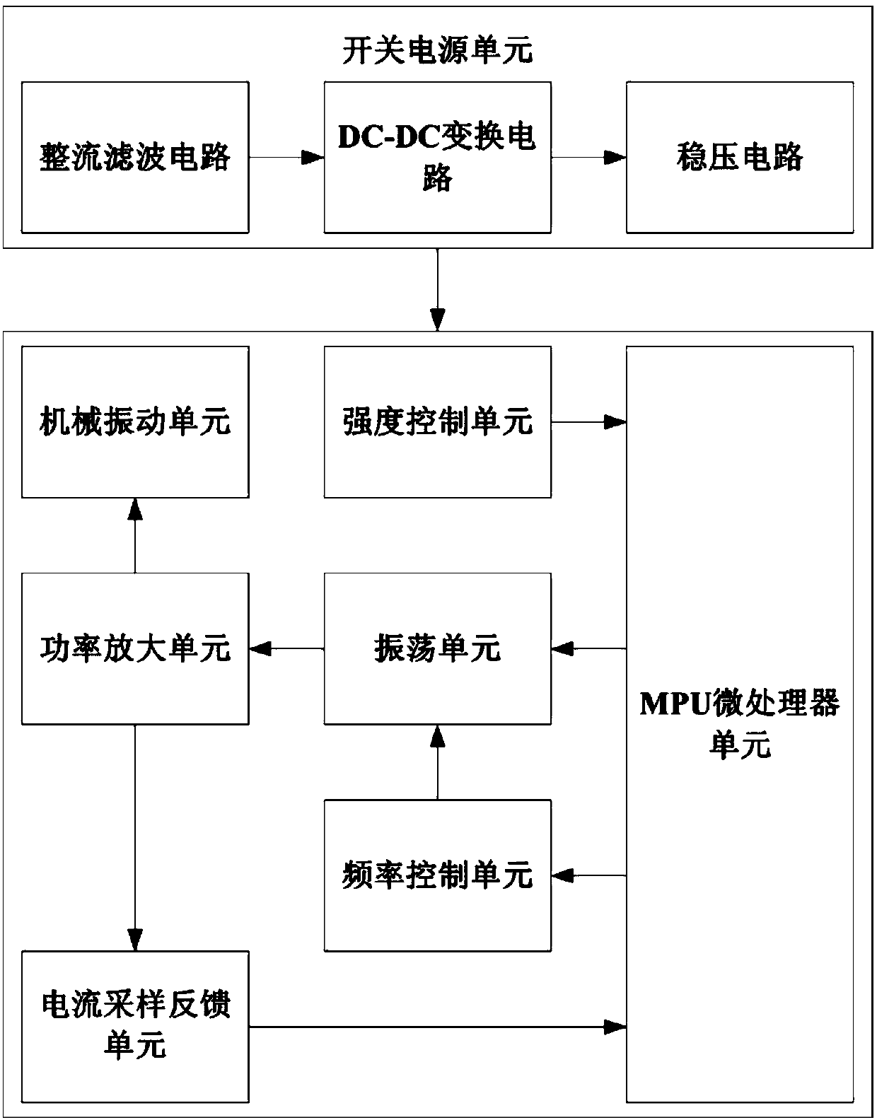
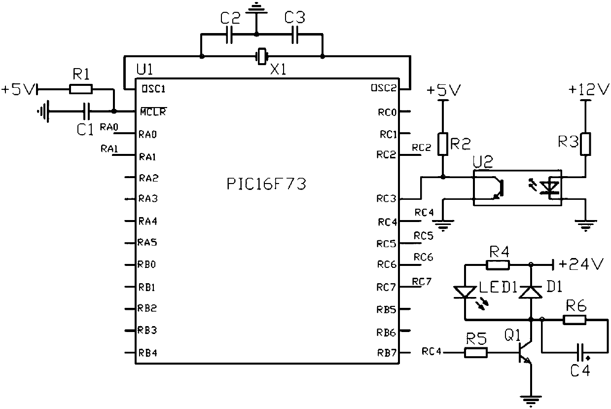
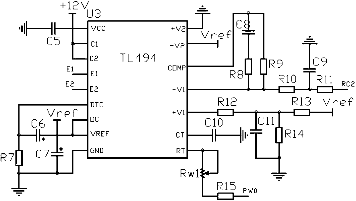
[0029] Such as figure 1 As shown, a low-temperature-rise self-adaptive ultrasonic dental scaler includes an MPU microprocessor unit, an oscillation unit, a frequency control unit, an intensity control unit, a power amplification unit, a current sampling feedback unit, a mechanical vibration unit and a switching power supply unit; The unit generates a push-pull pulse output with a controllable duty ratio under the control of the MPU microprocessor unit, and the MPU microprocessor unit sends data to the frequency control unit to control the oscillation frequency of the oscillation unit, so that the oscillation signal generated by the oscillation unit occupies The air ratio and frequency are controlled by the MPU microprocessor unit, and the oscillation signal is amplified by the power amplifier unit to drive the mechanical vibration ...


PUM


Abstract

The invention provides a light temperature increase self-adaptive ultrasonic dental descaler which comprises an MPU (microprocessor unit), an oscillating unit, a frequency control unit, an intensity control unit, a power amplifying unit, a current sampling and feedback unit, a mechanical oscillation unit and a switching power supply unit. According to the dental descaler, an optimum resonance point can be automatically scanned and searched, number lock is performed on the resonance frequency and the oscillation intensity, the drifting of the resonance point is minimal, the working efficiency is high, and the stability and the reliability are improved; dirt such as dental plaque, dental calculus and the like can be well eliminated, so that an effect of beautifying teeth is achieved; a switching power supply is adopted as a power supply, so that the heat generated by the power supply part is reduced, and therefore, the temperature in the dental descaler is low, and the service life of the dental descaler is prolonged.

Description

technical field [0001] The invention relates to the technical field of medical plastic and cosmetic equipment, in particular to a low-temperature-rise self-adaptive ultrasonic tooth scaler. Background technique [0002] Ultrasonic tooth scaler is a tooth cleaning machine used in the process of ultrasonic tooth cleaning. It drives the tooth cleaning tip through ultrasonic waves, and extends the vibrating tooth scale tip into the oral cavity to loosen plaque, tartar, and fine tartar and teeth. The adhesive on the tooth surface breaks down the dirt on the tooth surface, and at the same time, it is continuously rinsed with water to remove the calculus on the tooth surface and complete the tooth cleaning. [0003] The oscillating signal of the existing ultrasonic tooth scaler is usually directly generated by the single-chip microcomputer controller. Although this method is simple and convenient, there are two defects: first, the push-pull oscillating signal cannot be generated, s...

Claims


Application Information

Patent Timeline
IPC IPC(8): A61C17/20
Inventor 陈美金
Owner HUZHOU HUINENG ELECTROMECHANICAL TECH CO LTD
Learn More