Train-mounted transformer magnetizing inrush current suppression method and combined circuit breaker system

An exciting inrush current and transformer technology, applied in the field of circuit breaker control systems, can solve problems such as insulator damage, high-speed train impact, insulator melting or fragmentation, etc.

Inactive Publication Date: 2018-01-12
CENT SOUTH UNIV
View PDF2 Cites 5 Cited by
  • Summary
  • Abstract
  • Description
  • Claims
  • Application Information

AI Technical Summary

Problems solved by technology

The arc generally bypasses the insulator and is generated along the surface of the insulator, thus causing damage to the insulator. For example, the high temperature of the arc will melt or crack the insulator, thereby causing damage to personal, life and property safety.
[0004] When the train starts or the circuit breaker needs to be used to complete the circuit closing operation immediately after the phase is over, when the circuit breaker is closed, due to the sudden voltage change on the primary side of the transformer, the traction transformer will be oversaturated, thereby generating a very large excitation inrush current, excitation The magnitude of the inrush current is generally more than five times the rated current, which will have a very strong impact on the high-speed train and cause the relay to malfunction

Method used


Image

  • Train-mounted transformer magnetizing inrush current suppression method and combined circuit breaker system
  • Train-mounted transformer magnetizing inrush current suppression method and combined circuit breaker system
  • Train-mounted transformer magnetizing inrush current suppression method and combined circuit breaker system

Examples


Embodiment Construction

[0048] A specific implementation of a method for suppressing inrush current of a train-mounted transformer and a combined circuit breaker system according to the present invention will be given below in conjunction with the accompanying drawings, but the implementation of the present invention is not limited to the following embodiments.

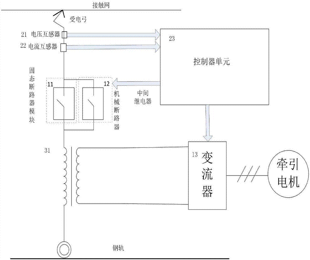
[0049] figure 1 A system structure diagram of a method for suppressing inrush current of a train vehicle-mounted transformer and a combined circuit breaker system provided by the present invention. Its structural composition includes two parts: the main circuit and the control circuit. Devices, etc.; control circuits include controllers, voltage sensors, current sensors, etc.

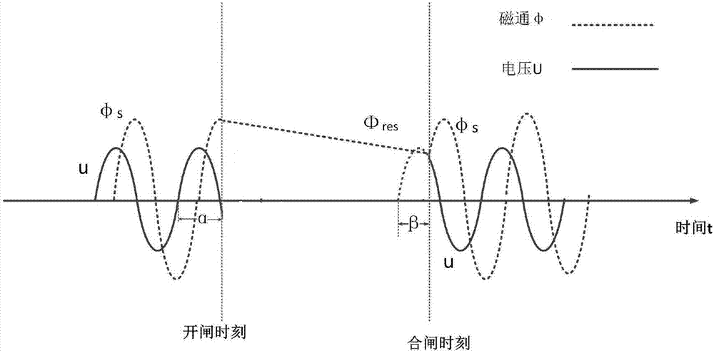
[0050] figure 2 The present invention provides a schematic diagram of a method for suppressing the inrush current of a train-mounted transformer and a phase-selection closing control strategy algorithm for a combined circuit breaker system. The invention adopts a p...


PUM


Abstract

The invention discloses a train-mounted transformer magnetizing inrush current suppression method and a combined circuit breaker system which have a function of suppressing train-mounted transformer magnetizing inrush current. The combined circuit breaker system structurally comprises a control loop and a main circuit, the control loop comprises a controller, a voltage sensor and a current sensor,and the main circuit comprises a solid-state circuit breaker and a mechanical circuit breaker. The invention further provides new circuit breaker system topology. A phase selection making control strategy is adopted to suppress train-mounted transformer magnetizing inrush current, in other words, at the moment of opening the combined circuit breaker, residual magnetism is calculated according toa relation between flux and voltage phase and recorded; at the moment of closing of the next time, circuit breaker closing phase angle is calculated through the residual magnetism and attenuation coefficient thereof, and a calculating principle is enabling stable-state flux at the moment of closing and residual magnetism of a transformer to have no error to achieve the objective of suppressing themagnetizing inrush current. A solid-state circuit breaker module is added into the main circuit, so that response speed is increased while resistance to voltage and current of the circuit breaker system is ensured.

Description

technical field [0001] The invention relates to a circuit breaker control system with the function of suppressing excitation inrush current and an implementation method, belonging to the technical field of circuit breakers. Background technique [0002] As a switching device that can close the circuit and carry the inrush current, the circuit breaker is widely used in the train traction drive control system. [0003] It is necessary to use the circuit breaker to complete the circuit shut-off operation immediately before the train stops or passes the phase. When the circuit breaker is opened, the air is ionized and becomes a conductor due to the voltage exceeding the tolerance of the air to generate an arc. The arc generally bypasses the insulator and generates along the surface of the insulator, thus causing damage to the insulator. For example, the high temperature of the arc will melt or crack the insulator, thereby causing damage to the safety of people, life and property...

Claims


Application Information

Patent Timeline
IPC IPC(8): H02H9/02B60L9/00
Inventor 李志勇席凯龙
Owner CENT SOUTH UNIV
Why Eureka
Try Eureka