Inrush current suppression device suitable for testing transformer frequent no-load input

A technology for testing transformers and magnetizing inrush currents, applied in emergency protection circuit devices, circuit devices, emergency protection circuit devices for limiting overcurrent/overvoltage, etc. Simple, simple structure effect

Active Publication Date: 2014-09-24
XJ ELECTRIC
View PDF8 Cites 0 Cited by
  • Summary
  • Abstract
  • Description
  • Claims
  • Application Information

AI Technical Summary

Problems solved by technology

[0005] The purpose of the present invention is to provide an excitation inrush suppression device suitable for frequent no-load input of test transformers, so as to solve the problem of complex control and operation of existing excitation inrush suppression devices

Method used


Image

  • Inrush current suppression device suitable for testing transformer frequent no-load input
  • Inrush current suppression device suitable for testing transformer frequent no-load input
  • Inrush current suppression device suitable for testing transformer frequent no-load input

Examples


Embodiment Construction

[0016] The present invention will be further introduced below in conjunction with the drawings and specific embodiments.

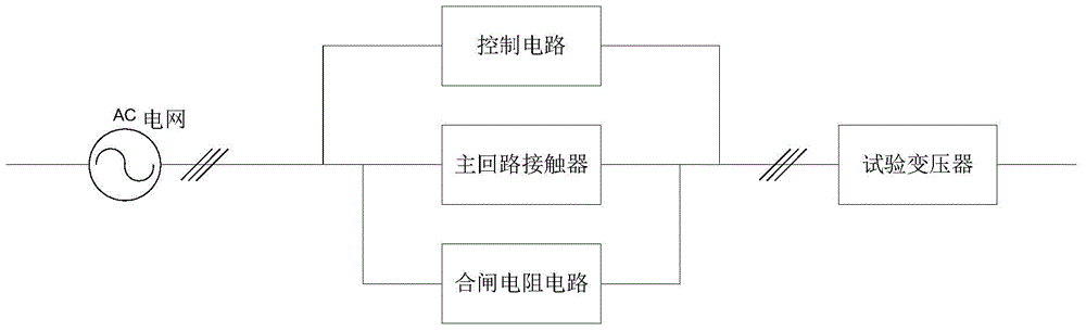
[0017] Such as figure 1 As shown, the present invention is a schematic diagram of the excitation inrush current suppression device of the present invention. It can be seen from the figure that the device includes a main circuit contactor connected in series on the transmission line between the power grid and the transformer, and the main circuit contactor is connected in parallel. The brake resistance circuit, the main circuit contactor and the closing resistance circuit are all controlled by the control circuit.

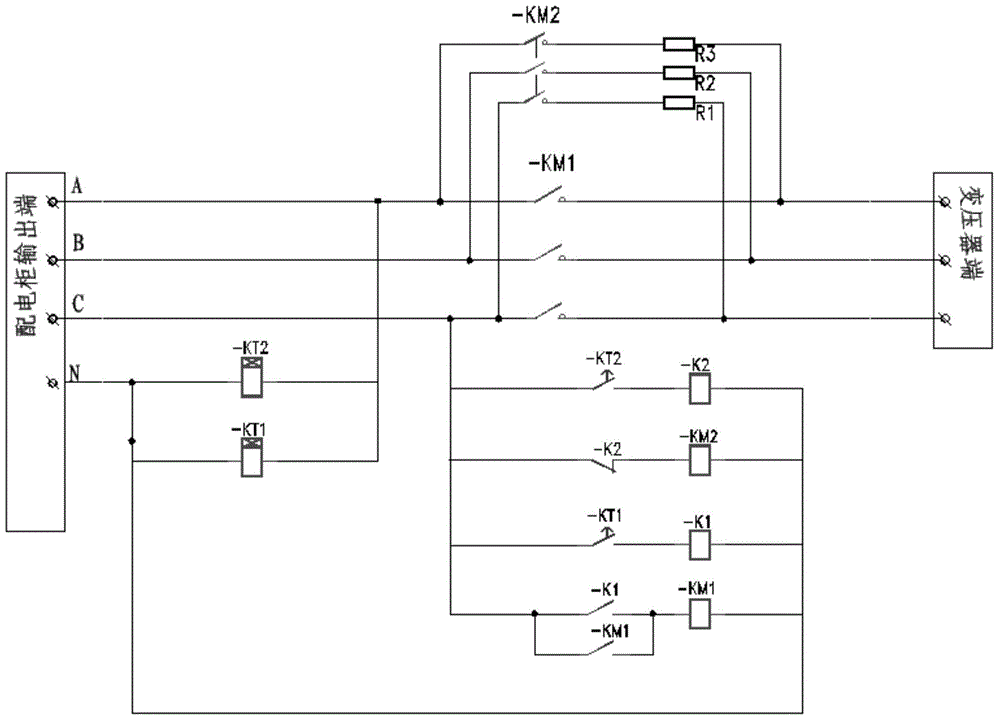
[0018] Such as figure 2 Shown is a circuit diagram of an embodiment of an excitation inrush current suppression device suitable for frequent no-load input of test transformers according to the present invention. It can be seen from the figure that the device includes the main contact of the main circuit contactor KM1 connected in series on the transm...


PUM


Abstract

The invention discloses an inrush current suppression device suitable for testing transformer frequent no-load input. The device is completely serially connected into a power supply loop, the protection and operation method of the original power supply and distribution system will not be changed, so advantages of simple transformation and convenient operation can be realized; and the control circuit is composed of a time relay and a contactor, so advantages of simple structure and no complex digital control can be realized, and the time of the time relay can be adjusted according to actual needs to satisfy the transformer soft starting requirements of different rated capacities and currents, so the device has advantages of broad applicability and wide application range, and play an important support and guarantee in the test of the whole high-power power electronic equipment.

Description

Technical field [0001] The invention relates to an excitation inrush current suppression device suitable for frequent no-load input of test transformers. Background technique [0002] When the transformer is running in a steady state without load, its current is 0.35% to 10% of the rated current. However, when the transformer is closed at no load or light load, the magnetic flux saturation of the iron core will cause an inrush current to appear at the moment of closing. The value can reach 8-30 times the rated current of the transformer, which will seriously endanger the life of the transformer. And cause the transformer protection device to malfunction, the circuit breaker switch is frequently damaged, and the magnetizing inrush current is fed back to the grid, which seriously affects the power quality of the grid. At present, the manufacture of high-power power electronic equipment requires complete test equipment and test systems. The test transformer is very important. At th...

Claims


Application Information

Patent Timeline
Patent Type & Authority Applications(China)
IPC IPC(8): H02H9/02
Inventor 龚晓伟王景丹张学成常忠廷屈路军汪海涛焦照旭白金刚
Owner XJ ELECTRIC
Why Eureka
Try Eureka