Torsion damper assembly for crankshaft

A torsional shock absorber and crankshaft technology, which is applied in the direction of spring/shock absorber, vibration suppression adjustment, portable lifting device, etc., can solve the problem of cogging runout accuracy and reduce the crankshaft torsional shock absorber assembly in the axial direction. Series motion and torsional vibration amplitude, vibration damping rubber ring shear fatigue and other issues, to achieve the effect of reducing torsional vibration, improving reliability and fatigue life

Inactive Publication Date: 2018-01-12
CHONGQING CHANGAN AUTOMOBILE CO LTD
View PDF5 Cites 1 Cited by
  • Summary
  • Abstract
  • Description
  • Claims
  • Application Information

AI Technical Summary

Problems solved by technology

It solves the problem that the runout accuracy of the existing medium cogging is difficult to be guaranteed, improves a level of accuracy, helps reduce the wear of the toothed pulley, and greatly reduces the axial series motion and torsional vibration of the crankshaft torsional damper assembly Increase the vibration amplitude, prolong the service life of various components of the crankshaft system, and reduce engine noise
But none of them involve how to solve the problem that the vibration damping rubber ring in the existing crankshaft torsional damper assembly is prone to shear fatigue

Method used


Image

  • Torsion damper assembly for crankshaft
  • Torsion damper assembly for crankshaft
  • Torsion damper assembly for crankshaft

Examples


Embodiment Construction

[0020] The present invention will be further described below in conjunction with accompanying drawing.

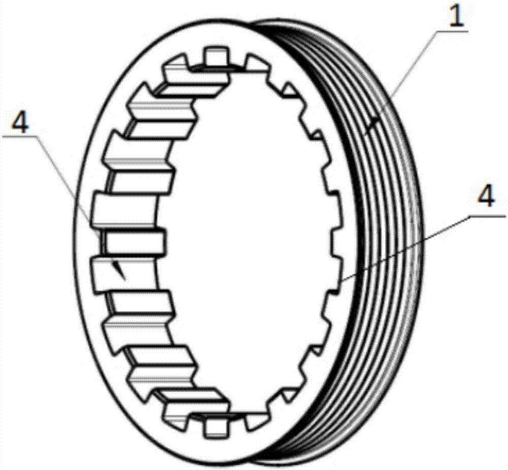
[0021] see figure 1 A crankshaft torsional damper assembly shown includes a pulley 1 and a hub 3 that is mated with the crankshaft, and is characterized in that: it also includes a pulley located between the inner circle of the pulley 1 and the outer circle of the hub 3 The damping rubber ring 2.

[0022] see figure 2 , the inner circle of the pulley 1 is equidistantly provided with a plurality of large grooves 4 of the same size, and the outer circle is provided with belt grooves.

[0023] see image 3 , the outer circle of the vibration-damping rubber ring 2 is equidistantly provided with a plurality of large bosses 5 of the same size, and the inner circle is equidistantly provided with a plurality of small grooves 6 of the same size, and each of the large bosses 5 Number is equal to the number of the large groove 4;

[0024] see Figure 4 , the outer circle of the...


PUM


Abstract

The invention relates to a torsion damper assembly for a crankshaft. The torsion damper assembly for the crankshaft comprises a belt wheel, a wheel hub connected with the crankshaft in a matched modeand a damping rubber ring arranged between the inner circle of the belt wheel and the outer circle of the wheel hub. Multiple large grooves with the same size are formed in the inner circle of the belt wheel at equal distance. Multiple large bosses with the same size are arranged on the outer circle of the damping rubber ring at equal distance, and multiple small grooves with the same size are formed in the inner circle of the damping rubber ring at equal distance. Multiple small bosses with the same size are arranged on the outer circle of the wheel hub at equal distance. The large bosses arranged on the outer circle of the damping rubber ring correspond to the large grooves formed in the inner circle of the belt wheel one to one and are in interference fit with the large grooves formed in the inner circle of the belt wheel; and the small bosses arranged on the outer circle of the wheel hub correspond to the small grooves formed in the inner circle of the damping rubber ring and are in interference fit with the small grooves formed in the inner circle of the damping rubber ring. According to the torsion damper assembly for the crankshaft, the shear force borne by the damping rubber ring can be converted into the pressure, the service life of the damping rubber ring is prolonged, torsional vibration of the crankshaft is significantly reduced, and the reliability of an engine isimproved.

Description

technical field [0001] The invention relates to an engine, in particular to a crankshaft torsional damper assembly in an engine crankshaft transmission. Background technique [0002] The function of the crankshaft torsional damper assembly is to transmit the crankshaft torque to water pumps, hydraulic pumps, generators and other components through the belt and drive them to work. Harm and reduce vehicle vibration and noise. When the automobile engine is working, the magnitude and direction of the force acting on the crankshaft are periodically changed, and the crankshaft will produce torsional vibration due to the swing of the flywheel with a large moment of inertia; this torsional vibration will greatly affect the ride of the vehicle comfort, and even affect the operation of the entire power output and transmission system. Therefore, the crankshaft torsional damper assembly is now widely used in high-performance engines. Now the most widely used is to connect the pulley ...

Claims


Application Information

Patent Timeline
IPC IPC(8): F16F15/124F16F15/126F16H55/40
Inventor 肖祥邓伟林翰徐丽茹伍建撰薛东升
Owner CHONGQING CHANGAN AUTOMOBILE CO LTD
Why Eureka
Try Eureka