
Continuous monitoring device and method for radioactive gas

A technology of radioactive gas and monitoring device, applied in the field of nuclear power, can solve the problems of inability to correctly and completely display composition information, inability to distinguish the activity value of nuclide, influence analysis of radiation effects, etc., so as to reduce the detection lower limit and improve reliability. degree, the effect of saving economic costs

Active Publication Date: 2018-01-09
中广核工程有限公司 +1
View PDF5 Cites 4 Cited by
  • Summary
  • Abstract
  • Description
  • Claims
  • Application Information

AI Technical Summary

Problems solved by technology

However, the above-mentioned monitoring method has the following deficiencies: first, the continuous measuring device is used to detect the total activity, which cannot distinguish the activity values ​​of each nuclide, and cannot directly detect the existence of the Kr-85 nuclide, resulting in inaccurate detection results; Secondly, the spectral analysis method performed quarterly usually uses a 3L standard steel cylinder for sampling, and the sampled gas is placed on a high-purity germanium gamma spectrometer for measurement, because the gamma decay branches of some nuclides are relatively small, lower than those of high-purity germanium The lower limit of detection of the gamma spectrometer prevents the spectral analysis results from correctly and completely displaying the composition information of the measured airborne flow, which affects the analysis of the radiation impact of the airborne effluent of the nuclear power plant

Method used


Image

  • Continuous monitoring device and method for radioactive gas

Examples


Embodiment Construction

[0036] In order to make the purpose of the invention, technical solution and beneficial technical effects of the present invention clearer, the present invention will be further described in detail below in conjunction with the accompanying drawings and specific implementation methods. It should be understood that the specific implementations described in this specification are only for explaining the present invention, not for limiting the present invention.

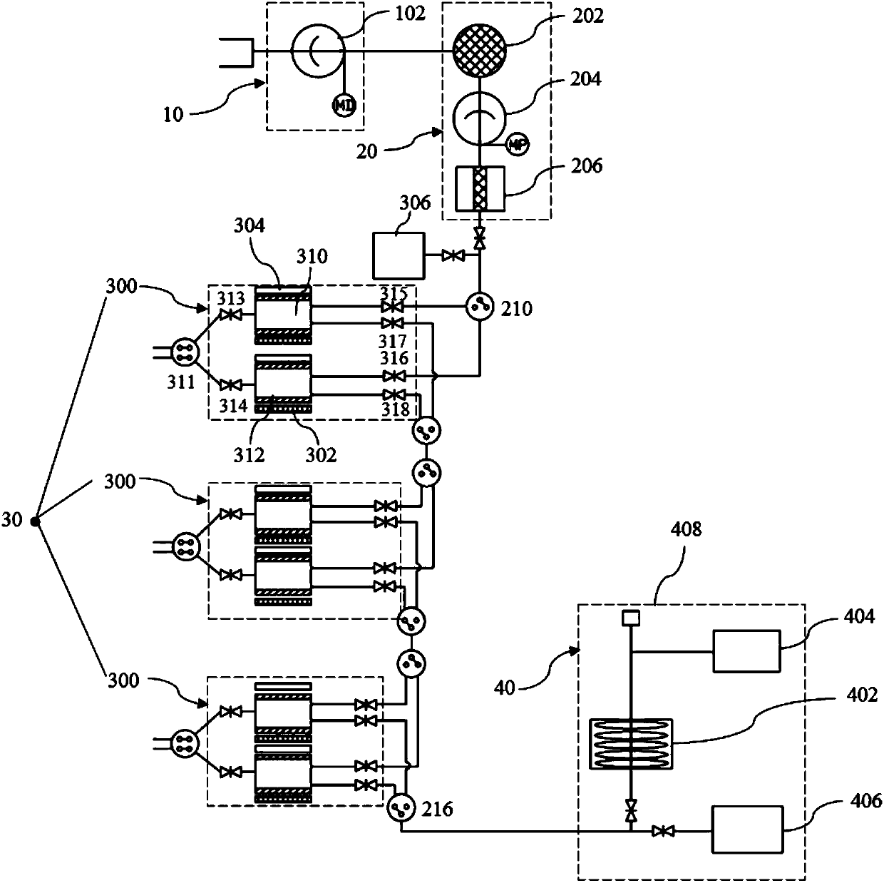
[0037] see figure 1 Shown, the radioactive gas continuous monitoring device of the present invention comprises:

[0038] The sampling unit 10 includes an air extraction pump 102 connected to the exhaust chimney through an air sampling line;

[0039] The adsorption filtration unit 20 is connected with the suction pump 102, and includes a molecular sieve 202, a compression pump 204 and a polymer permeable membrane 206 connected in sequence;

[0040] The activated carbon adsorption unit 30 is connected to the polymer per...


PUM


Abstract

The invention discloses a continuous monitoring device for radioactive gas. The device comprises a sampling unit, an adsorption and filtration unit, an activated carbon adsorption unit and a separation and monitoring unit, wherein the sampling unit comprises a suction pump connected with an exhausting chimney through a gas extracting pipeline; the adsorption and filtration unit is connected with the suction pump and comprises a molecular sieve, a compression pump and a macromolecular infiltration membrane which are connected sequentially; the activated carbon adsorption unit is connected withthe macromolecular infiltration membrane and comprises at least one mutually connected activated carbon adsorption assembly; the separation and monitoring unit is connected with the at least one activated carbon adsorption assembly and comprises a chromatographic column and a detection device which are connected sequentially. Compared with the prior art, the continuous monitoring device for radioactive gas is provided with multiple activated carbon adsorption assemblies which alternately operate and adopts a temperature swing adsorption principle, so that the concentration of radioactive gas is gradually increased, and the continuity and the accuracy of monitoring are guaranteed. Besides, the invention further discloses a continuous monitoring method for radioactive gas.

Description

technical field [0001] The invention belongs to the technical field of nuclear power. More specifically, the invention relates to a radioactive gas continuous monitoring device and method, which are suitable for continuous and accurate measurement of airborne radioactive effluents in nuclear power plants, and are also suitable for monitoring radioactive gases other than nuclear power plants. Nuclear facilities for airborne radioactive effluent demand. Background technique [0002] During the operation of nuclear power plants, the radioactive substances that need to be discharged subsequently enter the environment through liquid effluents and gaseous effluents, which may cause radiation impacts on the public. Therefore, the discharge of radioactive effluents from nuclear power plants should adopt dose control, total discharge control and discharge concentration control standards, and the total annual discharge control value of inert gases in airborne radioactive effluents is ...

Claims


Application Information

Patent Timeline
Patent Type & Authority Applications(China)
IPC IPC(8): G01N30/02G01N30/06
Inventor 高耀毅熊军陈小强魏学虎尹淑华吕炜枫贾运仓
Owner 中广核工程有限公司
Learn More