
High-efficiency drying and stirring device

A stirring device, high-efficiency technology, applied in the direction of drying, drying machine, drying solid materials, etc., can solve the problems affecting the drying efficiency and the transmission ratio of the device, so as to improve water evaporation, reduce energy consumption and facilitate operation Effect

Inactive Publication Date: 2018-01-09
浦江县协盈动物饲料技术开发有限公司
View PDF6 Cites 4 Cited by
  • Summary
  • Abstract
  • Description
  • Claims
  • Application Information

AI Technical Summary

Problems solved by technology

However, in the actual use process, the belt of the drying device of the invention may slip on the driving and driven wheels, which may affect the transmission ratio of the device and affect the drying efficiency

Method used


Image

  • High-efficiency drying and stirring device
  • High-efficiency drying and stirring device
  • High-efficiency drying and stirring device

Examples


Embodiment 1

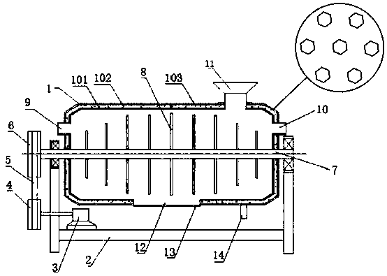
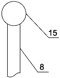
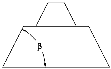
[0019] Such as Figure 1~3 As shown, a high-efficiency drying and stirring device includes a frame 2 and a drying box 1 arranged on the upper end of the frame 2. The upper end of the frame 2 is provided with a motor 3, and the motor 3 is connected to a rotating shaft 7, and the rotating shaft 7 is arranged on the drying box 1. In the center of the interior, a rotating rod 8 is connected to the surface of the rotating shaft 7, and the two ends of the rotating shaft 7 protrude from the drying box 1 and are fixed with the frame 2. The upper end of the drying box 1 is provided with a feed port 11, and the left side of the drying box 1 is provided with an air inlet 9. The air outlet 10 is provided on the right side of the drying box 1, and the material outlet 12 and the water outlet 14 are provided at the bottom of the drying box 1. The structure of the device is simple, easy to install and operate, and the structure of the frame 2 is stable, which can effectively support the rotati...

Embodiment 2

[0028] Such as Figure 1~3 As shown, a kind of high-efficiency drying and stirring device, when grain is dry, the dustproof cover 13 of material outlet 12 is closed, the dustproof cover of water outlet 14 is opened, and feed inlet 11 and air inlet 9 and outlet are pulled out. The dust-proof plug inside the tuyere 10 is used to pour grain into the drying box 1 from the feed port 11, turn on the motor 3 to make it work, the output shaft of the electrical appliance 3 drives the driving wheel 4 to rotate, and the driving wheel 4 drives the driven wheel through the belt 5 6 rotates, the driven wheel 6 makes the rotating shaft 7 rotate, and then the rotating rod 8 on the rotating shaft 7 turns the grain, and simultaneously feeds hot air into the air inlet 9, and the hot air passes through the grain and blows out from the air outlet 10 after taking away the moisture. The air is absorbed by the box of the drying box 1, and is conducted to the outside of the drying box 1 to evaporate, ...


PUM

PropertyMeasurementUnit
angleaaaaaaaaaa

Abstract

The invention provides a high-efficiency drying and stirring device. The high-efficiency drying and stirring device comprises a machine frame and a drying box arranged at the upper end of the machineframe, a motor is arranged at the upper end of the machine frame, a rotary shaft is connected to the motor, the rotary shaft is arranged at the center of the interior of the drying box, and a rotatingrod is connected to the surface of the rotary shaft. The two ends of the rotary shaft extend out of the drying box and are fixed to the machine frame, a feeding port is formed in the upper end of thedrying box, an air inlet is formed in the left side of the drying box, an air outlet is formed in the right side of the drying box, and a discharging port and a water outlet are formed in the bottomof the drying box. The high-efficiency drying and stirring device is simple in structure, and convenient to mount and operate, the transmission ratio from the motor to the rotary shaft is high, the stirring effect is good, the positions of the inlets and outlets formed in the surface of the drying box are reasonable, the dustproof effect is good, and the dustproof effect, the dehumidification effect and the drying effect can be achieved effectively.

Description

technical field [0001] The invention belongs to the technical field of drying, and in particular relates to a high-efficiency drying and stirring device. Background technique [0002] Drying equipment is also called dryer and dryer. The equipment used for drying operation, the moisture in the material (generally refers to water or other volatile liquid components) is vaporized and escaped by heating to obtain a solid material with a specified moisture content. The purpose of drying is to meet the needs of material use or further processing. For example, the drying of wood before making wooden molds and wooden utensils can prevent product deformation, and the drying of ceramic blanks before calcination can prevent cracking of finished products. In addition, the dried materials are also convenient for transportation and storage, such as drying the harvested grains below a certain moisture content to prevent mildew. Since natural drying is far from meeting the needs of produ...

Claims


Application Information

Patent Timeline
Patent Type & Authority Applications(China)
IPC IPC(8): F26B11/16F26B25/04C09D167/08C09D5/08C09D7/61C09D7/63
Inventor 陈义娜
Owner 浦江县协盈动物饲料技术开发有限公司
Learn More