Device capable of enabling crosshead and piston rod of compressor to be connected stably

A crosshead and piston rod technology, which is used in the field of devices for stable connection between the compressor crosshead and the piston rod, can solve the problem that the piston rod and the crosshead cannot be locked with each other, so as to improve reliability, safety, and tightening. Good effect, the effect of protecting the teeth

Inactive Publication Date: 2018-01-09
BENGBU GAOKE ENERGY EQUIP
View PDF0 Cites 1 Cited by
  • Summary
  • Abstract
  • Description
  • Claims
  • Application Information

AI Technical Summary

Problems solved by technology

[0004] The technical problem to be solved by the present invention is to provide a device that stabilizes the connection between the compressor crosshead and the piston rod, which can solve the problem that the piston rod and the crosshead cannot be locked to each other in small and medium-sized compressors

Method used


Image

  • Device capable of enabling crosshead and piston rod of compressor to be connected stably
  • Device capable of enabling crosshead and piston rod of compressor to be connected stably
  • Device capable of enabling crosshead and piston rod of compressor to be connected stably

Examples


Embodiment 1

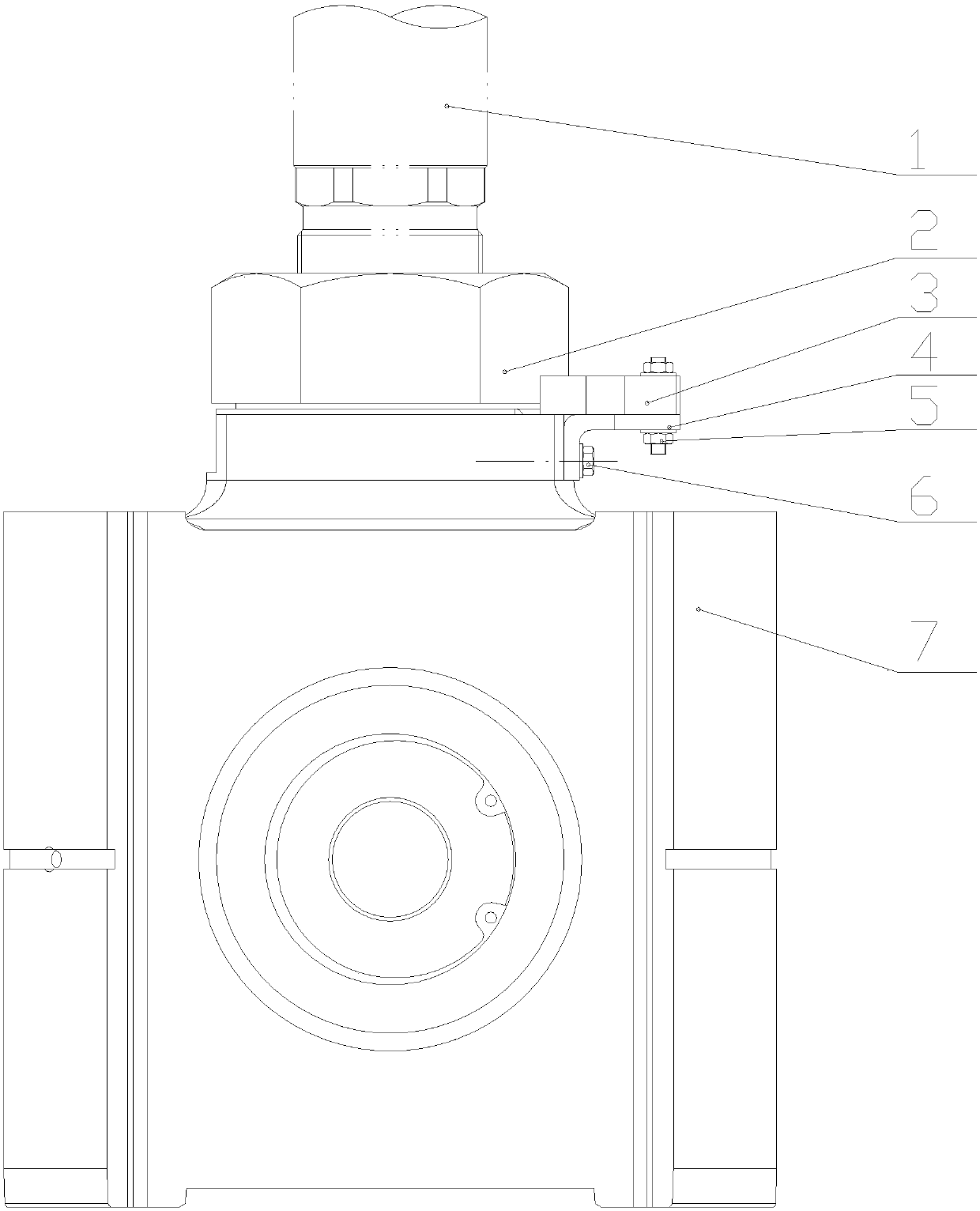
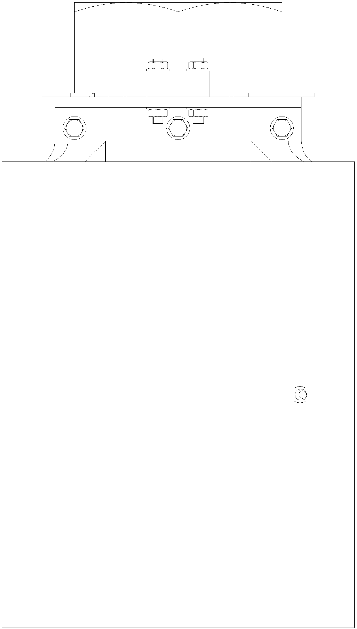
[0019] refer to Figure 1-3 , a device for stabilizing the connection between the compressor crosshead and the piston rod, including a fastening steel plate 3, a right-angle steel plate 4 and a crosshead body 7, which is vertically drilled and installed on the right side of the crosshead pin hole at the top of the crosshead body 7 The internally threaded hole of the right-angle steel plate 4 is drilled on the vertical plate of the right-angle steel plate 4 vertically corresponding to the position of the internal thread hole of the crosshead body 7 tops. The position of the hole on the corresponding right-angle steel plate 4 transverse plates is drilled. The holes on the fastening steel plate 3 and the holes on the vertical plate and the transverse plate of the right-angle steel plate 4 are all through holes.

[0020] The hole on the vertical plate of the right-angle steel plate 4 is the same size as the internal threaded hole at the top of the crosshead body 7, and the hole o...

Embodiment 2

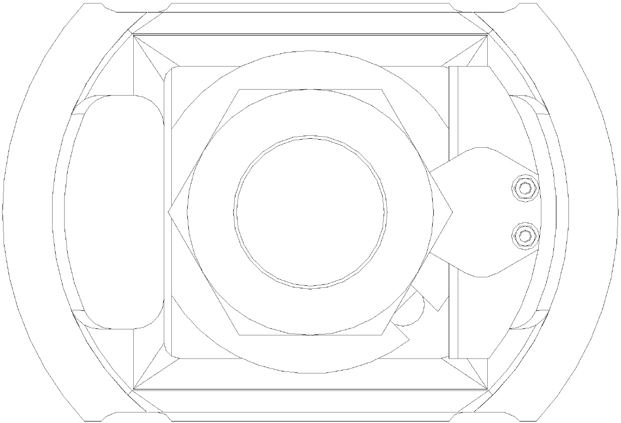
[0023] refer to Figure 1-4 , a device for stabilizing the connection between the compressor crosshead and the piston rod, including a fastening steel plate 3, a right-angle steel plate 4 and a crosshead body 7, which is vertically drilled and installed on the right side of the crosshead pin hole at the top of the crosshead body 7 The internally threaded hole of the right-angle steel plate 4 is drilled on the vertical plate of the right-angle steel plate 4 vertically corresponding to the position of the internal thread hole of the crosshead body 7 tops. The position of the hole on the corresponding right-angle steel plate 4 transverse plates is drilled. The holes on the fastening steel plate 3 and the vertical plates of the right-angle steel plates 4 and the holes on the transverse plates are all through holes, and the through holes on the vertical plates of the right-angle steel plates 4 are designed as counterbore holes.

[0024] The hole on the vertical plate of the right-...


PUM


Abstract

The invention discloses a device capable of enabling a crosshead and a piston rod of a compressor to be connected stably and relates to the field of small and medium size compressors. The device comprises a fastening steel plate, a right-angled steel plate and a crosshead body. An inner threaded hole for mounting the right-angled steel plate is drilled vertically in the right side of a pin hole ofthe crosshead at the top end of the crosshead body, a hole with the same dimension is drilled in the position, corresponding to the inner threaded hole in the top end of crosshead body, in a verticalplate of the right-angled steel plate, and the two holes are connected through a bolt; a hole is formed in a transverse plate of the right-angled steel plate, a hole is drilled in the position, corresponding to the hole in the transverse plate of the right-angled steel plate, in the fastening steel plate, and the holes are connected through a stud. In connection, the right-angled steel plate andthe fastening steel plate as well as a fastener are not directly connected to the piston rod, so that the reciprocating inertial force of the right-angled steel plate, the fastening plate and the fastener is relatively small, and the right-angled steel plate, the fastening plate and the fastener do not loosen if being fixed.

Description

technical field [0001] The invention relates to the field of small and medium-sized compressors, in particular to a device for stably connecting a crosshead of a compressor with a piston rod. Background technique [0002] In the connection between the connecting rod and the piston rod in the reciprocating compressor, the crosshead is often used to over-connect, and the piston rod is connected to the connecting rod through the crosshead so that the piston rod will not be subjected to the side pressure brought by the connecting rod. This way the friction between the piston and the cylinder is minimal. Moreover, the crosshead and the piston rod can only move axially, which can make full use of the volume of the cylinder, and the method of controlling the lubricating oil is relatively simple, which increases the efficiency of the compressor. Although there are many ways to connect the piston rod and the crosshead in reciprocating compressors, most of the connection methods are ...

Claims


Application Information

Patent Timeline
Patent Type & Authority Applications(China)
IPC IPC(8): F04B39/00
Inventor 高恒林赵英东邓衍亮孔验兵
Owner BENGBU GAOKE ENERGY EQUIP
Why Eureka
Try Eureka