Pot heat exchanger

A technology of heat exchangers and exchangers, applied in heat exchange equipment, heat exchangers, indirect heat exchangers, etc., to achieve low total system energy loss, uniform or balanced raw gas velocity, and reduce fouling

Inactive Publication Date: 2018-01-09
GENERAL ELECTRIC TECH GMBH
View PDF7 Cites 0 Cited by
  • Summary
  • Abstract
  • Description
  • Claims
  • Application Information

AI Technical Summary

Problems solved by technology

This occurs because raw gas collection piping and gas cleaning units can introduce flow resistance in the flue gas collection and cleaning system

Method used


Image

  • Pot heat exchanger
  • Pot heat exchanger
  • Pot heat exchanger

Examples


Embodiment Construction

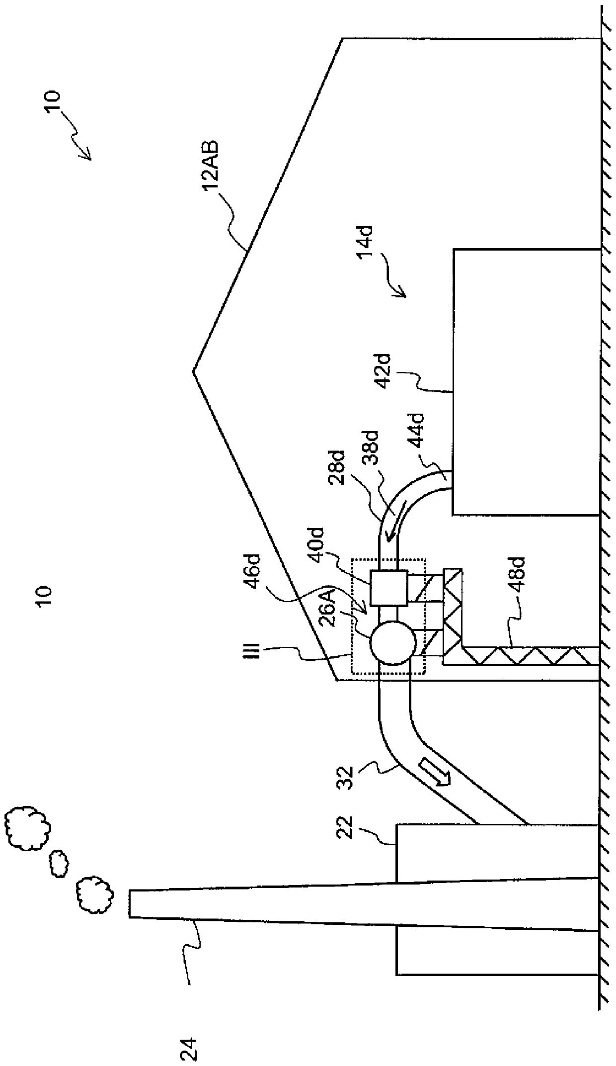
[0027] figure 1 It is a schematic diagram of the aluminum manufacturing plant 10 viewed from above. The aluminum manufacturing plant 10 includes a plurality of electrolytic cell rooms or electrolytic workshops 12AB, 12CD, and each electrolytic cell room includes a plurality of aluminum preparation smelting pots or electrolytic cells 14. The electrolysis cells 14 are arranged in the series of electrolysis cells in a manner well known to those skilled in the art. The series of electrolysis cells includes multiple electrolysis cells connected in series in a direct current (DC) loop. figure 1 The first electrolytic cell room 12AB and the second electrolytic cell room 12CD are shown, where each electrolytic cell room contains a corresponding series of electrolytic cells 16AB, 16CD. in spite of figure 1 The single electrolytic cell series 16AB, 16CD in are shown as being contained in a single electrolytic cell room 12AB, 12CD, but a single electrolytic cell series defined as a plural...


PUM


Abstract

The invention relates to a pot heat exchanger. A raw gas collection system for collecting raw gas from a plurality of aluminium smelting pots is equipped with a plurality of branch ducts (28d), each of which is arranged to channel a respective branch flow (38d) of raw gas from an aluminium smelting pot to a collection duct (26A), which is common to and shared by the branch ducts (28d). Each of said branch ducts (28d) is, near an outlet (52d) thereof, equipped with a curved section (50d) for aligning the branch flow (38d) with a flow direction of raw gas (27A) already present in the common collection duct (26A), and a constriction (54d) for accelerating the branch flow (38d) through the branch duct outlet (52d) into the common collection duct (26A). Furthermore, each of said branch ducts (28d) is equipped with a heat exchanger (40d) for removing heat from the respective branch flow (38d) of raw gas. The combined flow resistance of the constriction (54d) and the heat exchanger (40d) reduces the need for adjusting the respective branch flows (28d) using dampers, thereby reducing the power required to transport the raw gas.

Description

[0001] This application is a divisional application of the invention patent application with the application number 201180055198.8, the filing date of September 1, 2011, and the invention title of "Boiler Heat Exchanger". Technical field [0002] The present invention relates to a raw gas collection system for collecting raw gas from multiple aluminum smelting pots. The present invention also relates to a method for moving a side stream of raw gas from an aluminum smelting pot to a common collection pipe. Background technique [0003] Aluminum is generally prepared by an electrolysis method using one or more aluminum preparation electrolytic cells. Such an electrolytic cell usually includes a bath for containing bath contents containing fluoride-containing minerals on top of the molten aluminum. The contents of the bath are in contact with the cathode block and the anode block. The aluminum oxide is supplied to the bath at regular intervals via openings at several locations alon...

Claims


Application Information

Patent Timeline
Patent Type & Authority Applications(China)
IPC IPC(8): C25C3/22F27D17/00
CPCF27B14/08F27D17/001F27D17/004F28D7/1615F28D7/1653F28D21/0003F28F9/0282F28F13/08F28F19/00C25C3/22Y10T137/6416C25C7/06C25C3/06C25C3/24F27D17/002Y02P10/25
Inventor A.K.索尔胡斯G.维德O.E.比亚尔诺
Owner GENERAL ELECTRIC TECH GMBH
Why Eureka
Try Eureka