
Oil filter for eliminating lubricating oil film

A technology of oil filter and paint, which is applied in the direction of filtration and separation, filtration circuit, separation method, etc., can solve the problems of economic waste, reduce the purification degree of particle impurities, impurity filtration, etc., so as to prolong the service life and restore the physical and chemical Indicators, the effect of avoiding parts sticking

Pending Publication Date: 2018-01-09
昆山威胜达环保设备有限公司
View PDF7 Cites 1 Cited by
  • Summary
  • Abstract
  • Description
  • Claims
  • Application Information

AI Technical Summary

Problems solved by technology

The impurities in the oil are filtered out by the filter. After the impurities are removed, the purity of the oil depends entirely on the precision of the filter medium in the filter. If the precision of the filter medium is too low, the impurities in the oil cannot be filtered out; If the precision is too high, the resistance of the oil passing through the filter will increase, and the filter hole will be easily blocked by impurities, so the filter medium has to be replaced frequently, which will bring great inconvenience to daily use and cause huge economic waste.
[0004] The ionization oil purification device is mainly installed between the positive electrode plate and the negative electrode plate in the electrostatic box. The dust collecting plate is often connected in a chain between the positive electrode plate and the negative electrode due to the accumulation of particulate impurities in the oil. On the board, positive and negative ion connections often lead to conductive breakdown of the electrode plate, which greatly increases the maintenance cost of the purification equipment
In addition, the positive electrode plate and the negative electrode plate have a small area of ​​adsorption and accumulation of particulate impurities in the oil, which reduces the purity of the purification of particulate impurities in the oil.
Therefore, there are disadvantages of high maintenance cost and low purification purity.

Method used


Image

  • Oil filter for eliminating lubricating oil film
  • Oil filter for eliminating lubricating oil film

Examples


Embodiment

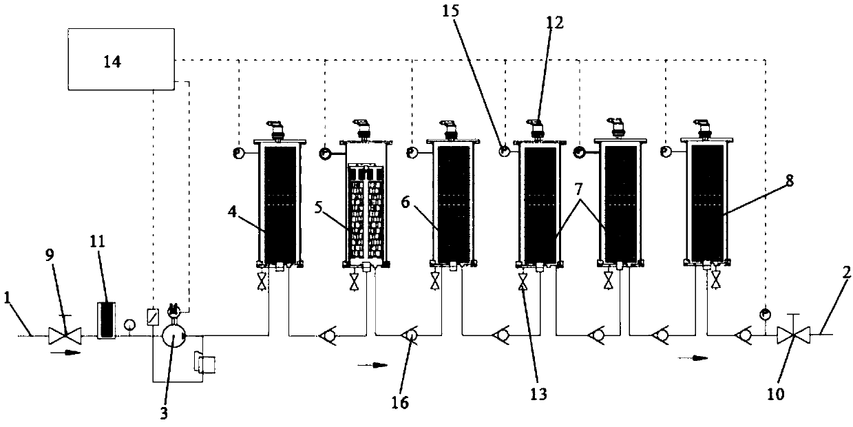
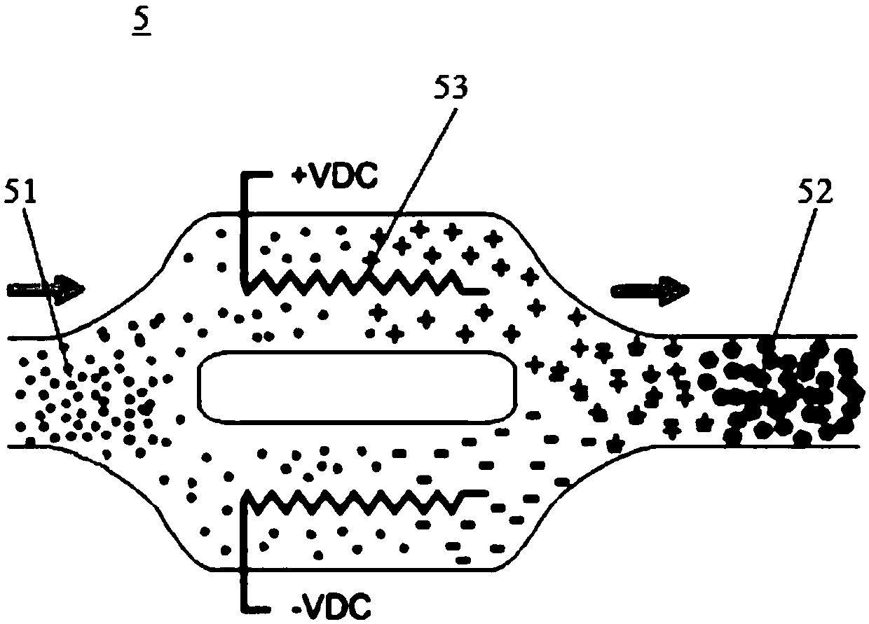
[0026] Please refer to Figure 1-Figure 2 , the present embodiment is an oil filter for removing lubricating paint film, which includes an oil inlet pipeline 1, an oil outlet pipeline 2 and an oil pump 3 arranged on the oil inlet pipeline 1, between the oil inlet pipeline 1 and the oil outlet pipeline 2 A first pre-filter 4 , a charging mixer 5 , a second pre-filter 6 , an exchange resin filter unit 7 and a protection filter 8 are sequentially arranged in between.

[0027] Between the first pre-filter 4 and the charging mixer 5, between the charging mixer 5 and the second pre-filter 6, between the second pre-filter 6 and the exchange resin filter unit 7, between the exchange resin filter unit 7 and the protection A one-way valve 16 is arranged on the communication pipe between the filters 8 and the interior of the exchange resin filter unit 7 to prevent backflow, guarantee the normal operation of the oil filter unit, and improve its safety.

[0028] The fluid passes through t...


PUM


Abstract

The invention discloses an oil filter for eliminating a lubricating oil film. The oil filter comprises an oil inlet pipeline, an oil outlet pipeline and an oil pump arranged on the oil inlet pipeline,and further comprises an electrical control device which is electrically connected with the oil pump, wherein a first prefilter, a charging mixer, a second prefilter, an exchange resin filtering unitand a protection filter are sequentially arranged between the oil inlet pipeline and the oil outlet pipeline; pressure sensors are arranged on the first prefilter, the second prefilter, the exchangeresin filtering unit and the protection filter; and the electrical control device is electrically connected with the pressure sensors. The oil filter disclosed by the invention has the performance ofpeeling and cleaning the oil sludge / film in the system and is safe; and moreover, the sampling pollution degree at any part of the whole system after purification is less than or equal to NAS 5 level,and the membrane propensity score (MPC) is less than 10.

Description

【Technical field】 [0001] The invention belongs to the technical field of oil stain purification, in particular to an oil filter for removing lubricating paint film. 【Background technique】 [0002] At this stage, there are two main ways for oil purifiers to purify oil, one is vacuum filtration purification, and the other is ionization purification, but both have their own shortcomings. [0003] The vacuum filtration and purification device is mainly composed of a coarse filter, a vacuum pump, a heating device, a vacuum exhaust device, a filter, and an oil storage tank. The impurities in the oil are filtered out by the filter. After the impurities are removed, the purity of the oil depends entirely on the precision of the filter medium in the filter. If the precision of the filter medium is too low, the impurities in the oil cannot be filtered out; If the precision is too high, the resistance of the oil passing through the filter will increase, and the filter hole will be eas...

Claims


Application Information

Patent Timeline
Patent Type & Authority Applications(China)
IPC IPC(8): B01D36/00
Inventor 刘威赖晓燕
Owner 昆山威胜达环保设备有限公司
Learn More