
Upward-inlet-type air suction distributor for compressor condensing unit

A technology for a condensing unit and a compressor, which is applied in the field of compressors, can solve the problems of affecting the quality of the compressor, high gas pressure, easy oil intake, etc., and achieves the effects of simple structure, low cost and ingenious conception.

Inactive Publication Date: 2018-01-05
TIANJIN DANHUA HONGYE REFRIGERATION TECH CO LTD
View PDF0 Cites 0 Cited by
  • Summary
  • Abstract
  • Description
  • Claims
  • Application Information

AI Technical Summary

Problems solved by technology

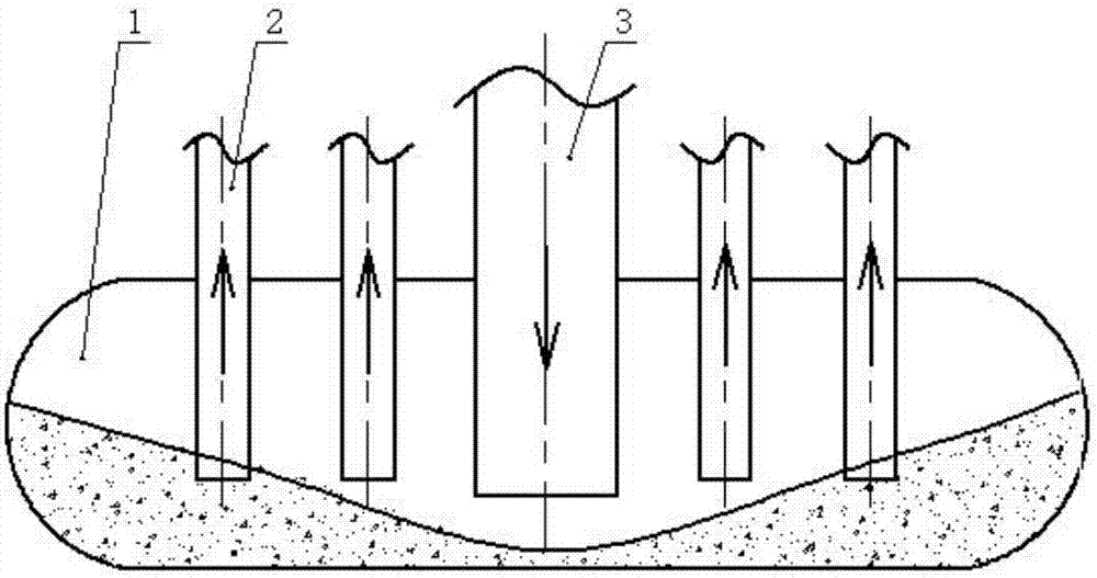
[0004] The problem existing in the above structure is: because the gas is discharged from the bottom end of the air return main pipe, and the gas pressure is relatively high, the oil at the bottom of the suction manifold is blown to both sides, making it easy to enter the bottom of the branch pipe at both ends. Oil, thus affecting the quality of the compressor

Method used


Image

  • Upward-inlet-type air suction distributor for compressor condensing unit
  • Upward-inlet-type air suction distributor for compressor condensing unit

Examples


Embodiment Construction

[0013] The present invention will be further described in detail below in conjunction with the accompanying drawings and through specific embodiments.

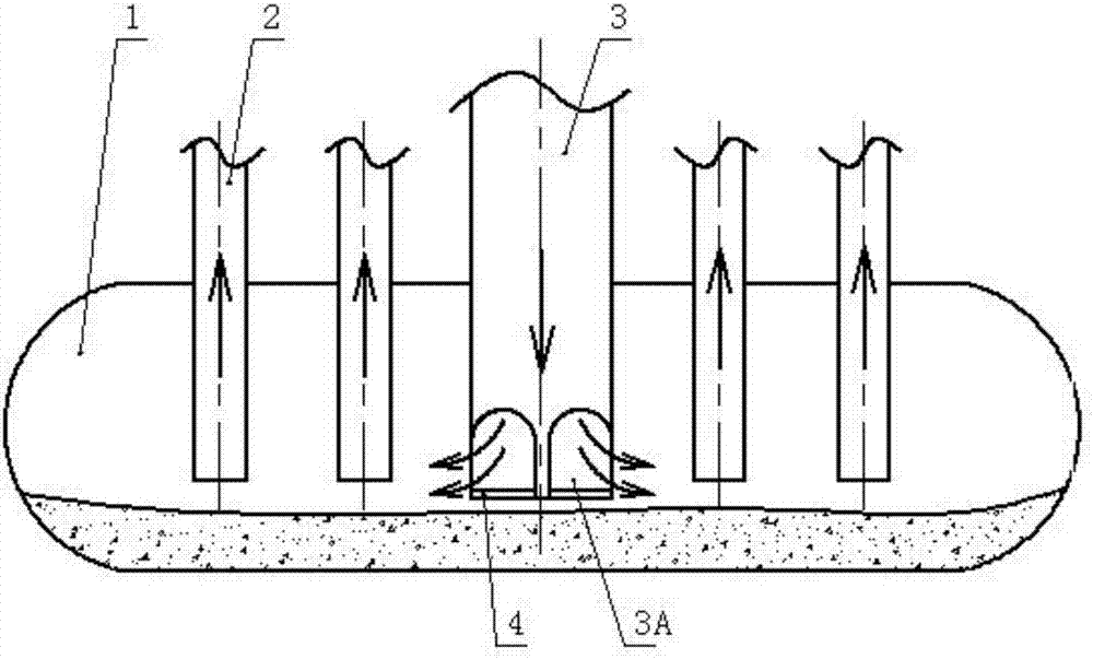
[0014] An upward suction distributor of a compressor condensing unit, such as figure 2 As shown, it includes a suction manifold 1, a branch pipe 2 and a return air manifold 3. The upper part of the suction manifold is vertically connected to the return air manifold, and the suction manifolds on the left and right sides of the return air manifold are vertical A plurality of branch pipes are connected and installed at intervals.

[0015] The innovation point of the present invention is:

[0016] The structure of the air return main pipe is as follows: the side wall of the bottom end of the air return main pipe embedded in the suction manifold is uniformly formed with a plurality of long air outlet holes 3A, and the bottom end of the air return main pipe is fixed with a circular plug with the same diameter. plate 4.

[0017] ...


PUM


Abstract

The invention relates to an upward-inlet-type air suction distributor for a compressor condensing unit. The upward-inlet-type air suction distributor comprises an air suction collecting pipe, branch pipes and an air return main pipe. The air return main pipe is installed on the upper portion of the air suction collecting pipe in a vertical communicating mode, and the multiple branch pipes are installed on the positions, on the left side and the right side of the air return main pipe, of the air suction collecting pipe at intervals in a vertical communicating mode; and according to the structure of the air return main pipe, a plurality of air outlet long holes are evenly manufactured in the side wall of the bottom end of the air return main pipe embedded in the air suction collecting pipe,and a circular blocking plate with the same diameter as the air return main pipe is fixedly installed at the bottom end of the air return main pipe. In the upward-inlet-type air suction distributor, the air outlet holes of the air return main pipe adopt a side wall air outlet mode, oil at the bottom of the air suction collecting pipe is prevented from being stamped due to the large pressure, and the normal oil surface inside the air suction collecting pipe is ensured to prevent fluctuation of the oil surface, so that the oil is prevented from entering the branch pipes; and the upward-inlet-type air suction distributor is simple in structure, scientific and reasonable in design, ingenious in concept, easy to achieve and low in cost and has wide application and popularization value.

Description

technical field [0001] The invention belongs to the technical field of compressors, in particular to an upward suction distributor of a condensing unit of a compressor. Background technique [0002] The compressor sucks the lower-pressure working medium vapor from the evaporator, raises its pressure, and then sends it to the condenser, where it is condensed into a higher-pressure liquid, which becomes a higher-pressure liquid after being throttled by the throttle valve. After the low-pressure liquid is sent to the evaporator, it absorbs heat and evaporates in the evaporator to become a steam with a lower pressure, thereby completing the refrigeration cycle. [0003] The compressor condensing unit includes a suction header 1 and a return air header 3, the return air header is vertically installed on the upper part of the suction header, such as figure 1 As shown, the suction headers on the left and right sides of the air return main pipe are vertically spaced and communicate...

Claims


Application Information

Patent Timeline
Patent Type & Authority Applications(China)
IPC IPC(8): F25B41/00F25B41/42
Inventor 肖鹏
Owner TIANJIN DANHUA HONGYE REFRIGERATION TECH CO LTD
Learn More