
Luminescent ceramic, LED packaging structure and preparation method of luminescent ceramic

A technology of luminescent ceramics and lasers, which is applied in semiconductor devices, electrical components, circuits, etc., can solve the problems of white LED color ring and affect the color uniformity of the light angle, and achieve the effect of uniform color and good luminous efficiency

Active Publication Date: 2020-05-15
JIANGSU LUOHUA NEW MATERIAL
View PDF6 Cites 0 Cited by
  • Summary
  • Abstract
  • Description
  • Claims
  • Application Information

AI Technical Summary

Problems solved by technology

However, since the refractive index of the grain boundary of fluorescent transparent ceramics is much higher than that of air, when the ceramic body is used as the light source of the phosphor body, a total reflection effect will occur, and a part of the light with a large incident angle cannot be refracted into the air, and can only be reflected back into the ceramic body Emitted from the side or reabsorbed into heat, this phenomenon seriously affects the color uniformity of the light output angle, resulting in a color ring in the white LED

Method used


Image

  • Luminescent ceramic, LED packaging structure and preparation method of luminescent ceramic
  • Luminescent ceramic, LED packaging structure and preparation method of luminescent ceramic
  • Luminescent ceramic, LED packaging structure and preparation method of luminescent ceramic

Examples


preparation example Construction

[0035] The present invention also provides a preparation method of luminescent ceramics, comprising:

[0036] Prepare luminescent ceramic raw materials;

[0037] The luminescent ceramic raw material is irradiated with a predetermined specification laser, and a depression is processed on the surface of the luminescent ceramic raw material;

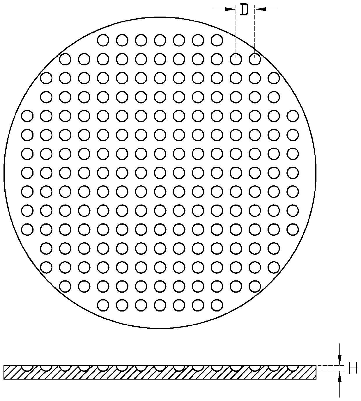
[0038] The surface of the luminescent ceramic raw material is scanned and irradiated with the predetermined specification laser in a fast scanning mode, and a plurality of the depressions are processed on the surface of the luminescent ceramic raw material, and the depressions are arranged in an orderly manner on the surface of the luminescent ceramic raw material. The ratio of the diameter to the depth of each depression is between 2:1 and 3:1 to prepare the luminescent ceramic;

[0039] The parameters of the laser of the predetermined specification include: the laser pulse duration is 20-100 ns, the pulse repetition rate is 1 kHz, the po...

Embodiment 1

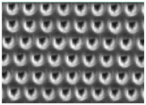
[0048] Ce is obtained by vacuum heat treatment 3+ The Φ15mm transparent YAG ceramic with a molar concentration of 0.3% was ground and polished to obtain a ceramic sheet with a thickness of 0.3mm. The polished transparent ceramic surface was irradiated with a 355nm laser pulse. The laser pulse duration was 40ns, the pulse repetition rate was 1kHz, the power was 0.2W, and the diameter of the laser spot was 10μm. The obtained hemispherical concave diameter D was about 15 μm, the depth H is approximately equal to 5 μm. Control the spacing distance between each depression a=b=20μm, obtain the sequence distribution of depressions by fast scanning mode, and then soak and wash in 98wt% concentrated sulfuric acid solution at 70°C for 1min, and finally obtain as follows: Figure 3a and Figure 3b The surface topography of the luminescent ceramic after treatment is shown.

[0049] The luminescent ceramic prepared in Example 1 was packaged into an LED light source for testing. The wave...


PUM

PropertyMeasurementUnit
thicknessaaaaaaaaaa
diameteraaaaaaaaaa
depthaaaaaaaaaa

Abstract

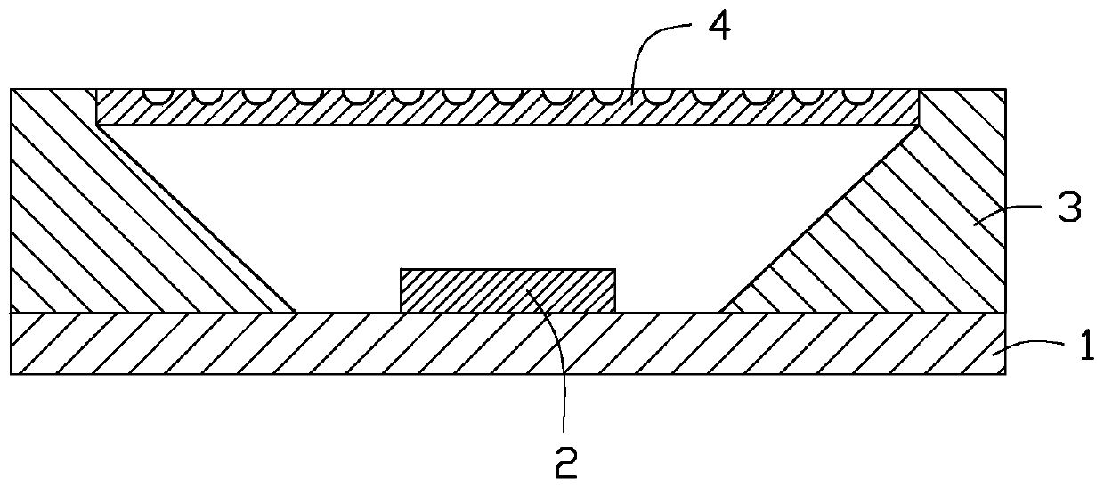
The invention provides luminescent ceramic. The surface of the luminescent ceramic is provided with multiple ordered concavities and each one of the concavities has a diameter-depth ratio of 2: 1 to 3: 1. The invention also provides an LED package structure of the luminescent ceramic and a preparation method of the luminescent ceramic. The luminescent ceramic can prevent light total reflection through adjustment of the diameter and depth of the concavities on the luminescent ceramic surface and realizes effective refraction of lights having large incident angles. The luminescent ceramic has good luminescent efficiency and even color.

Description

technical field [0001] The invention belongs to the field of material processing, and in particular relates to a luminescent ceramic, an LED packaging structure and a preparation method of the luminescent ceramic. Background technique [0002] Light-emitting diodes (LEDs) are known as a new generation of lighting sources because of their long service life, high efficiency, energy saving, and environmental protection. They have broad application prospects in the fields of lighting and backlight display. [0003] The traditional white light LED packaging method is to use phosphor powder and transparent silica gel material to mix and coat on the blue light chip, and obtain the white light LED by realizing the up-conversion of the blue light wavelength. However, when the light passes through, the phosphor will produce unavoidable phenomena such as scattering and absorption. In addition, the light scattered back to the LED chip and the substrate further leads to an increase in th...

Claims


Application Information

Patent Timeline
Patent Type & Authority Patents(China)
IPC IPC(8): C04B35/44C04B41/91H01L33/50
Inventor 罗雪方顾强瞿澄张甜甜
Owner JIANGSU LUOHUA NEW MATERIAL
Learn More