Internal combustion engine and method for detecting leak from crankcase and/or tank ventilation system

A crankcase ventilation, internal combustion engine technology, applied in crankcase ventilation, combustion air/combustion-air treatment, charging system, etc., can solve difficult monitoring, monitoring does not cause any problems, etc., to achieve simple cost, accurate detection of leakage Effect

Active Publication Date: 2018-01-02
BAYERISCHE MOTOREN WERKE AG
View PDF6 Cites 5 Cited by
  • Summary
  • Abstract
  • Description
  • Claims
  • Application Information

AI Technical Summary

Problems solved by technology

Although for the fuel tank ventilation line and / or the crankcase ventilation line and the lines that open into the intake line downstream of the throttle valve and are used to feed the exhaust gas to the In the intake line - the monitoring of the connection points does not cause any problems, but due to the sensor mechanism and construction it is only possible to monitor with difficulty the exhaust gas from the fuel tank leading into the intake line upstream of the compressor of the exhaust gas turbocharger Connections of lines and / or crankcase exhaust lines or lines through which the exhaust gas is introduced into the intake line during charging operation

Method used


Image

  • Internal combustion engine and method for detecting leak from crankcase and/or tank ventilation system
  • Internal combustion engine and method for detecting leak from crankcase and/or tank ventilation system
  • Internal combustion engine and method for detecting leak from crankcase and/or tank ventilation system

Examples


Embodiment Construction

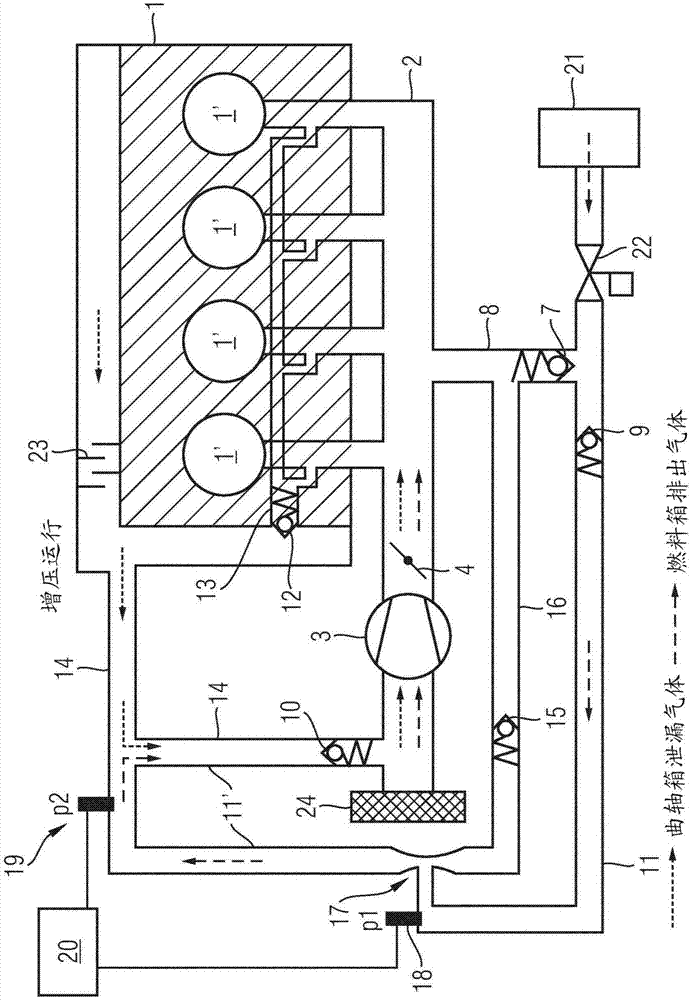
[0020] the following in Figures 1 to 3 In , the same reference numerals are applied to the same components.

[0021] figure 1 Shown is a schematic diagram of an internal combustion engine 1 according to the invention, which has, for example, four drawn cylinder blocks 1' denoted by circles and has a combustion air intake system 2 in which a combustion air intake system is arranged A compressor 3 (for example of an exhaust gas turbocharger) or a mechanical compressor, downstream of which a throttle (for example of a throttle valve) is arranged in the flow direction of the combustion air (indicated by the arrow in the compressor) Flow element 4. Furthermore, internal combustion engine 1 has a fuel tank ventilation system 5 for a fuel tank 21 and has a crankcase ventilation system 6 . The spatial separation of fuel tank ventilation system 5 and crankcase ventilation system 6 is indicated schematically by arrows.

[0022] The fuel tank ventilation system 5 can be connected to...


PUM


Abstract

The invention relates to an internal combustion engine with a combustion air intake system in which a compressor is arranged and in which a throttle element is arranged downstream of the compressor inthe flow direction of the combustion air. The internal combustion engine also comprises a tank ventilation system and a crankcase ventilation system. The tank ventilation system can be connected to the intake system downstream of the throttle element via a first non-return valve in a first line and upstream of the compressor via a second non-return valve in a second line and a third non-return valve in a second sub-line. The crankcase ventilation system can be connected to the intake system downstream of the throttle element via a fourth non-return valve in a third line and upstream of the compressor via a fourth line and the third non-return valve. The intake system can be connected to the second line downstream of the throttle element at a transitional point between the second line andthe second sub-line via a fifth non-return valve in a fifth line. A nozzle is formed at the transitional point from the fifth line to the second line and the second sub-line, and the second line opensinto the nozzle downstream of the second non-return valve. A first pressure sensor for measuring the pressure in the second line is provided in the second line between the second non-return valve andthe nozzle. By means of the internal combustion engine design according to the invention with a crankcase and a tank ventilation system and by means of the corresponding methods, only a single pressure sensor is required to diagnose or detect a leak. A second pressure sensor can be advantageously used to locate a leak.

Description

technical field [0001] The invention relates to an internal combustion engine with the features of the preamble of claim 1 and a method for detecting leaks in a crankcase ventilation system and / or a fuel tank ventilation system with the features of claim 6 . Background technique [0002] For this technical field, for example, German laid-open document DE 10 2009 008 831 A1 is mentioned, from which the present invention proceeds. An internal combustion engine is known from DE 10 2009 008 831 A1 with an intake line containing the compressor of the exhaust gas turbocharger and a throttle valve, as well as a fuel tank ventilation system and a crankcase ventilation system, the fuel tank The ventilation system and the crankcase ventilation system are connected to the intake line at two connections upstream of the compressor and downstream of the throttle valve. In order to be able to monitor the point of introduction of the exhaust gas into the intake line in a relatively simple ...

Claims


Application Information

Patent Timeline
IPC IPC(8): F02M25/08F01M13/02
CPCF01M13/023F01M2013/026F01M2013/027F02M25/0827F02M25/089F02M35/1038F01M13/022F01M13/028F01M13/04F01M2013/0044F01M2250/60F02M25/0836
Inventor R·比布尔J·格拉戴M·哈斯尔贝克S·雷纳
Owner BAYERISCHE MOTOREN WERKE AG
Why Eureka
Try Eureka