Fiber Optic Gyros Strapdown Inertial Measurement Device
A technology of fiber optic gyroscope and strapdown inertia, which is applied in the direction of Sagnac effect gyroscope, etc., can solve the problems of high manufacturing and processing precision of fiber optic gyroscope, long startup time, increased volume and power consumption, etc., and achieve high computing speed and reliability Increased performance, short start-up time, and weight reduction
Inactive Publication Date: 2016-10-05
BEIJING AEROSPACE TIMES OPTICAL ELECTRONICS TECH
View PDF0 Cites 10 Cited by
- Summary
- Abstract
- Description
- Claims
- Application Information
AI Technical Summary
Problems solved by technology
The United States uses this kind of measuring device on its tactical missiles. However, due to the relatively mature mechanical processing and manufacturing technology abroad, the error in installation and manufacturing is small, and the manufacturing and processing accuracy of the fiber optic gyroscope is high, and the temperature change has little influence on it. The design can fully meet the requirements of its rapid response, and its measurement accuracy is high
Since China's fiber optic gyro processing and manufacturing technology is relatively backward, if it is copied completely, although the reaction speed and measurement have been relatively improved, its temperature change has a great impact on the accuracy. In order to further achieve high measurement accuracy, the device needs to be equipped with a temperature Control device, that is, the entire fiber optic gyro instrument and accelerometer instrument components work in the constant temperature range, otherwise the accuracy cannot be guaranteed, which causes the relative increase in the measurement volume of the fiber optic inertial measurement, and the startup time is relatively long due to the temperature control device. For example, the "Design and Realization of the Fiber Optic Gyro Inertial Measurement Unit" disclosed in the first issue of P28-30 of "Chinese Journal of Habitual Measurement" in 1999, the research of Beijing University of Aeronautics and Astronautics adopts the above-mentioned scheme, and its response is about 20 minutes. Within half an hour, it is obviously difficult to meet the requirements of fast response and high measurement accuracy required by modern warfare; moreover, the three fiber optic gyroscopes in the measurement device all use DSP as the logic circuit, mainly through programming and executing program codes to complete digital operations , some auxiliary circuits need to be added to the periphery, resulting in increased volume and power consumption, making it difficult to further reduce costs, and it is not easy to achieve localization, which cannot meet the requirements of modern warfare for low cost, light weight, low power consumption and quick response to weapon systems
Method used
View moreImage
Smart ImageViewing Examples
Examples
Embodiment
Login to View More PUM
 Abstract
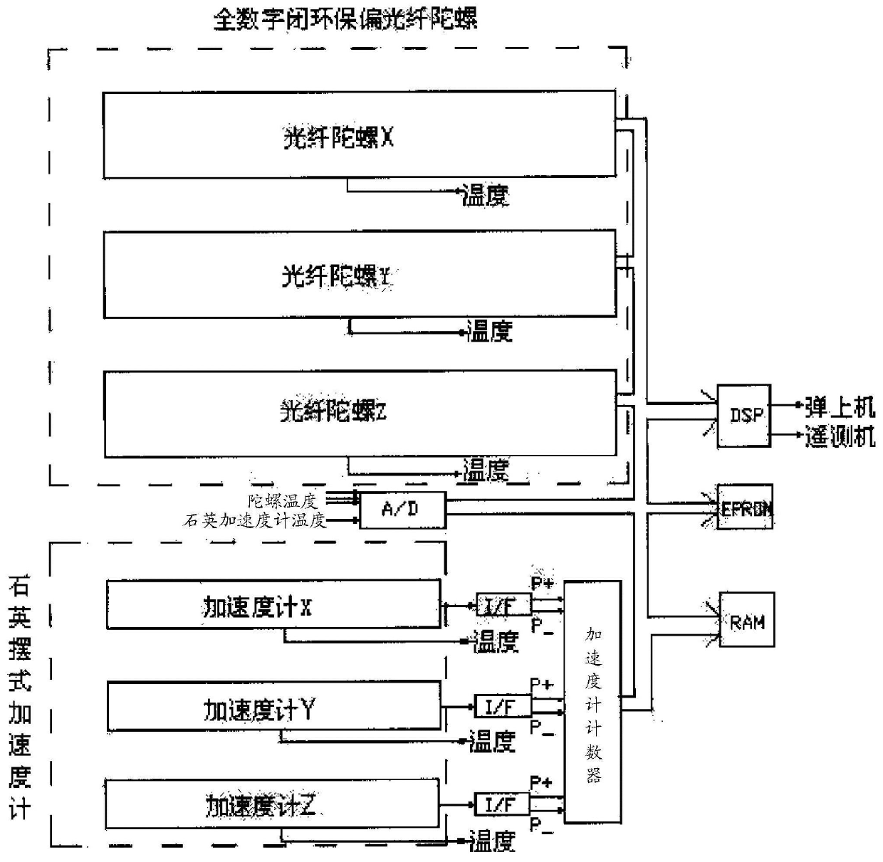
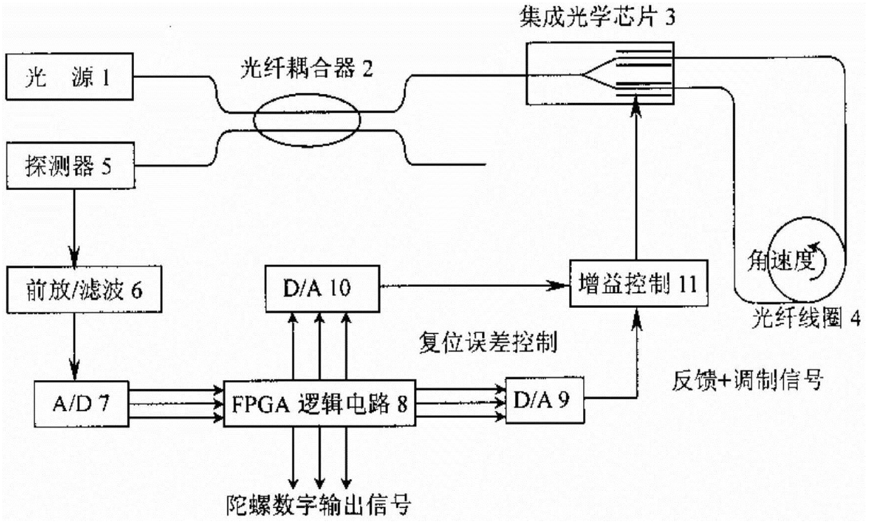
The fiber optic gyro strapdown inertial measurement device sets temperature measurement sensors inside three fiber optic gyroscopes and three quartz accelerometers, and performs zero temperature compensation on them by measuring the temperature changes of the fiber optic gyroscopes and quartz accelerometers, among which: the fiber optic gyroscope zero position The temperature compensation model is: Bf=KT0+KT1(T-T0), the quartz accelerometer zero temperature compensation model is: Ba=KaT0+KaT1(T-T0)+Kat2(T-T0)2 so that the measuring device can Working in the full temperature range, it avoids the disadvantages of the long thermal balance time of the temperature control scheme in the existing technology measuring device, so as to realize fast startup, and the full accuracy can be achieved within 3-5s after power-on; in addition, due to the use of FPGA-based fiber optic gyroscope On the one hand, the calculation speed and reliability of the gyroscope are greatly improved, and on the other hand, the size and weight of the gyroscope are reduced, which can especially meet the requirements of miniaturization and light weight of the weapon system.
Description
Technical field The invention relates to a miniaturized and fast-start fiber optic gyro strapdown inertial measurement device used for aircraft navigation, guidance and control in the field of aerospace. Background technique Because of the characteristics of good autonomy and all-weather work, inertial measurement devices have been widely used in the field of navigation and guidance of aerospace vehicles. It can continuously provide the position, speed and attitude information of the aircraft in real time, and guide the aircraft to reach the designated position. At present, the flexible strapdown inertial measurement device composed of flexible electromechanical gyroscope and quartz accelerometer is widely used, but the device composed of electromechanical gyroscope is difficult to achieve small size and Quick start can no longer meet the requirements of modern warfare for high integration and rapid response of weapon systems. For this reason, foreign countries began to use...
Claims
Login to View More Application Information
Patent Timeline
 IPC IPC(8): G01C19/64G01C19/72
Inventor 王巍张志鑫杨清生张红张元春王颂邦单联洁朱红生秦伟亮刘东伟
Owner BEIJING AEROSPACE TIMES OPTICAL ELECTRONICS TECH
Features
- R&D
- Intellectual Property
- Life Sciences
- Materials
- Tech Scout
- Unparalleled Data Quality
- Higher Quality Content
- 60% Fewer Hallucinations
Learn More Browse by: Latest US Patents, China's latest patents, Technical Efficacy Thesaurus, Application Domain, Technology Topic, Popular Technical Reports.
© 2025 PatSnap. All rights reserved.Legal|Privacy policy|Modern Slavery Act Transparency Statement|Sitemap|About US| Contact US: help@patsnap.com


