Quality control method of DNA (Deoxyribonucleic Acid) ploidy analysis equipment
A quality control method and analysis equipment technology, which is applied to the analysis of materials, material analysis through optical means, and measurement devices, etc., can solve the problems of inaccurate analysis results and achieve the effect of accurate and error-free analysis of samples
- Summary
- Abstract
- Description
- Claims
- Application Information
AI Technical Summary
Problems solved by technology
Method used
Image

Examples
specific Embodiment approach 1
[0032] Specific embodiment 1: A method for quality control of DNA ploidy analysis equipment includes the following steps:
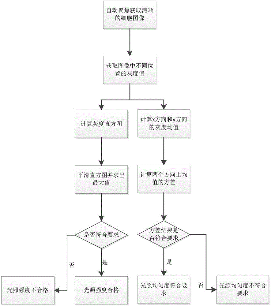
[0033] Step 1: Adjust the light source in the microscope by analyzing the pictures under the microscope field of view to make the light intensity and light uniformity meet the requirements;
[0034] If T low ≤p max ≤T high Then the light intensity meets the requirements, where T low ,T high Respectively represent the minimum and maximum of the light source intensity that meets the requirements, T low ,T high After many experiments and theoretical explorations, it can make the equipment operate normally, keep the image from being too dark or too bright, affecting the analysis of cells, and the result is within the allowable error range, and will not lead to misdiagnosis and missed diagnosis, p max Is p(p k ), p(p k ) Is the mean value of the number of pixels corresponding to the gray level in the smoothing window;
[0035] If both meet And The light is even...
specific Embodiment approach 2
[0045] Specific embodiment two: this embodiment is different from specific embodiment one in that the specific process of judging the intensity of light and the uniformity of light by analyzing the pictures under the microscope field in the first step is:
[0046] Step 1: Place the sample sheet on the platform and adjust the platform up and down to make a clear cell image under the camera's field of view (the collected cell image has a clear outline, no blur, and no blur, that is, the focus of the microscope objective lens coincides with the edge of the cell screen) ;
[0047] Step one and two: Grab the picture with the camera. The black and white picture of the cell under the microscope is represented by A0, A0(i,j) represents the gray level at the image position (i,j), 1≤i≤M,1≤j≤ N; M is the number of pixels in the horizontal direction in the captured image, and N is the number of pixels in the vertical direction in the captured image;
[0048] Step 13: Calculate the light intensi...
specific Embodiment approach 3
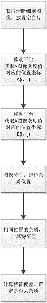
[0066] Specific embodiment three: This embodiment is different from specific embodiment one or two in that the specific process of determining the impurities in the optical path by analyzing the picture of the blank film under the mirror in the second step is:
[0067] Step 2: Place a blank film and adjust the platform up and down to make a clear cell image under the camera's field of view;
[0068] Step 2: Use the camera to capture the black and white picture under the microscope, denoted by A, A(i,j) represents the gray value at the image position (i,j), 1≤i≤M, 1≤j≤N;
[0069] Step two and three: control the electric platform to move a field of view, and use the camera to collect picture B;
[0070] Step two and four: Divide images A and B, and locate the impurity position; the impurity here may come from the light path or the blank film.
[0071] Step two and five: locate the position of impurities on A and B. For impurities at the same position on A and B, calculate the characterist...
PUM
 Abstract
Description
Claims
Application Information
 - Generate Ideas
- Intellectual Property
- Life Sciences
- Materials
- Tech Scout
- Unparalleled Data Quality
- Higher Quality Content
- 60% Fewer Hallucinations
Browse by: Latest US Patents, China's latest patents, Technical Efficacy Thesaurus, Application Domain, Technology Topic, Popular Technical Reports.
© 2025 PatSnap. All rights reserved.Legal|Privacy policy|Modern Slavery Act Transparency Statement|Sitemap|About US| Contact US: help@patsnap.com