


Quick Research
Generate reliable direction feasibility study reports for your R&D in just a few steps.

Technical Q&A
Discover and master advanced knowledge NOW. Basics, ideas, possibilities, all at once.

Find Solutions
As an expert in R&D theories, this can generate solutions to your technical problems instantly.

Evaluate Feasibility
Analyze your overall solution with one click, know your potential R&D risks in advance.

Monitor Landscape
Get weekly tech updates, stay abreast of the latest tech innovations and key insights.
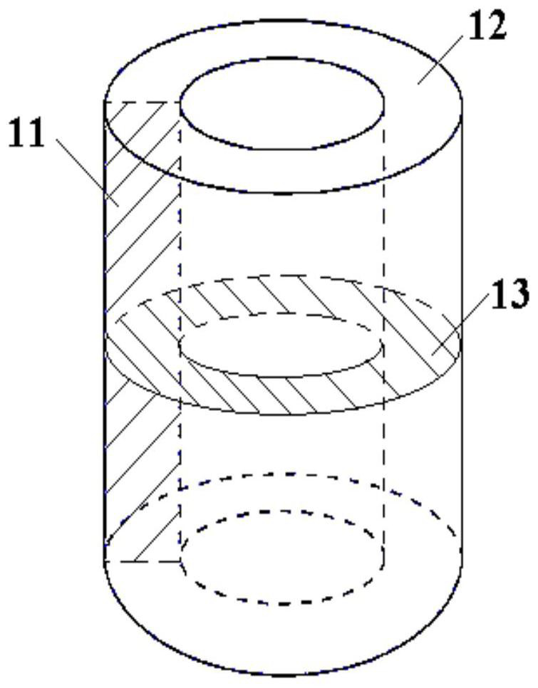
A Taylor-Couette experimental setup for solid-state media
An experimental device and medium technology, which is applied in the field of Taylor-Courette experimental devices, can solve the problems of being divided into two or more different types, and cannot realize the Taylor-Courte rheological experiment of liquid medium, so as to achieve comprehensive three-dimensional rheology The effect of form
- Summary
- Abstract
- Description
- Claims
- Application Information
AI Technical Summary
Problems solved by technology
Method used
Image

Examples
Embodiment 1
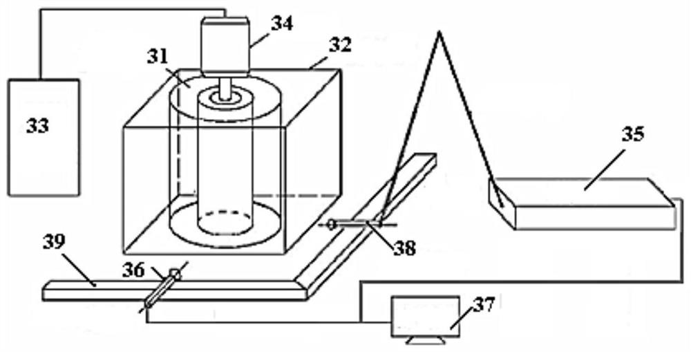
[0086] Use plasticine in red and blue colors (red corresponds to Figure 9 The brighter color in , blue corresponds to Figure 9 The darker color in the middle), respectively made the internal diameter is 20mm, the external diameter is 32mm, and the height is 10mm, and the fan-shaped cross-section cylinder with the central angle of 180 ° is loaded into the device through the above steps, and connected to each part of the device. Turn on the camera, and the gear transmission ratio used is 2:1, that is, the gear of the transmission part turns 2 times, and the gear of the main part turns 1 turn. The gear speed of the transmission part is 2 revolutions / min, the gear speed of the main part is 1 revolution / min, and the pressure exerted on the cylindrical plasticine is about 20N. After rotating for different numbers of turns, the experimental results are shown in the figure Figure 9 shown.
[0087] At the beginning, the two colors of plasticine were divided into two pieces of two...
Embodiment 2
[0089] Two materials, lead (Pb) and tin (Sn), are used to make a cylinder with an inner diameter of 47mm, an outer diameter of 51mm, and a height of 15mm, and divide the cylinder into four fan-shaped cross-section columns with a central angle of 90° Select two cylinders with a fan-shaped cross-section of lead and two cylinders with a fan-shaped cross-section of tin. The lead and tin are placed alternately to form a cylindrical sample. Such as Figure 10 shown. Put it into the sample chamber of the Taylor-Courtet experimental device of the present invention, adopt a pressurizing mechanism to pressurize the sample axially by 260KN, and after the inner and outer cylinder walls of the sample chamber are relatively rotated for 1 circle, take out the sample, and mechanically carry out the cross-section of the sample. Grinding and polishing, using a microscope to observe the flow form of the metal on the partial circular cross-section, the experimental results are as follows Figur...
PUM
| Property | Measurement | Unit |
|---|---|---|
| height | aaaaa | aaaaa |
Abstract
Description
Claims
Application Information
 - R&D Engineer
- R&D Manager
- IP Professional
- Industry Leading Data Capabilities
- Powerful AI technology
- Patent DNA Extraction
Browse by: Latest US Patents, China's latest patents, Technical Efficacy Thesaurus, Application Domain, Technology Topic, Popular Technical Reports.
© 2024 PatSnap. All rights reserved.Legal|Privacy policy|Modern Slavery Act Transparency Statement|Sitemap|About US| Contact US: help@patsnap.com