Crankshaft connecting rod cap assembly of cold header and mounting method thereof

A technology of crankshaft connecting rod and installation method, applied in the directions of engine components, engine lubrication, shafts, etc., can solve the problems of affecting the operation accuracy, affecting the accuracy, and the lubricating oil being easily taken out, so as to avoid the increase of friction and improve the The effect of heat dissipation

Pending Publication Date: 2017-12-29
SIJIN INTELLIGENT FORMING EQUIP CO LTD
View PDF5 Cites 0 Cited by
  • Summary
  • Abstract
  • Description
  • Claims
  • Application Information

AI Technical Summary

Problems solved by technology

[0003] 1) The heat dissipation effect is poor, which affects the accuracy. Since the connecting rod and the copper sleeve are in rigid contact during work, lubricating oil must be added to the shaft of the connecting rod to finally play a role in lubrication. However, at present, due to the length of the copper sleeve and the The length of the through hole of the connecting rod in the connecting rod cover is the same, so the entire copper sleeve covers the connecting rod, so that when the connecting rod reciprocates with the driver, the friction between the copper sleeve and the connecting rod will easily cause the connecting rod to Heat will affect the accuracy;
[0004] 2) The lubrication effect is poor, resulting in the wear of the copper sleeve and even the fatigue cracks of the connecting rod, which reduces its service life. Since the outer surface of the connecting rod is in full contact with the inner surface of the copper sleeve; there is no gap, and the lubricating oil is easy to be carried out , eventually leading to a period of time, the lubrication effect becomes worse, the friction increases, and affects the operation accuracy;
[0005] 3) When the connecting rod reciprocates, the heat dissipation effect of the whole connecting rod is poor

Method used


Image

  • Crankshaft connecting rod cap assembly of cold header and mounting method thereof
  • Crankshaft connecting rod cap assembly of cold header and mounting method thereof
  • Crankshaft connecting rod cap assembly of cold header and mounting method thereof

Examples


Embodiment 1

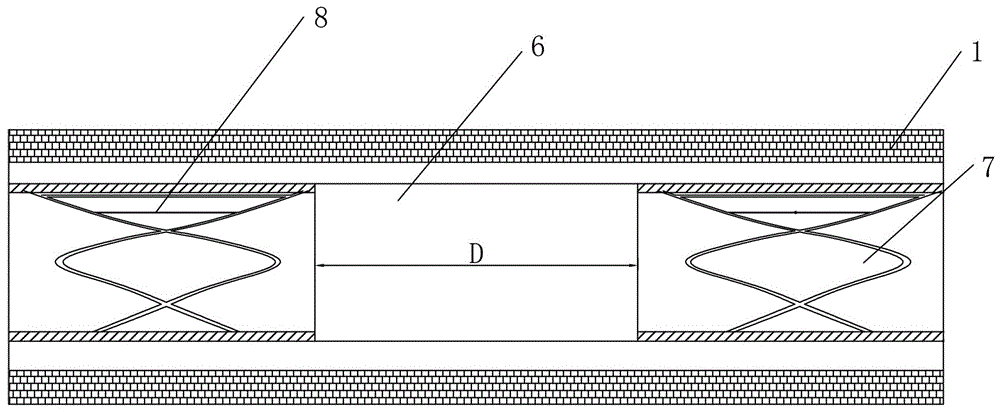
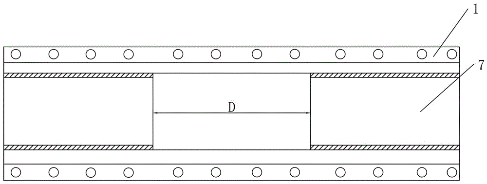
[0028] Such as figure 1 As shown, the crankshaft connecting rod cover assembly of a cold heading machine provided by this embodiment includes a body 1, and the connecting rod installation through hole 6 is arranged in the body 1, and the two axial ends of the connecting rod installation through hole 6 are More than two copper sleeves 7 are distributed at intervals, and an oil groove 8 is arranged on the inner wall of each copper sleeve 7 . In this embodiment, two copper sleeves 7 are distributed at the two axial ends of the connecting rod installation through hole 6 at intervals, and there is a distance of a certain length between the two copper sleeves 7. The number of copper sleeves 7 here is not correct for this embodiment The limitation of the invention is only considered as a preferred solution, and 3, 5 or more can be set in a specific embodiment.

[0029] This embodiment also discloses a method for installing a crankshaft connecting rod cover assembly of a cold heading...

Embodiment 2

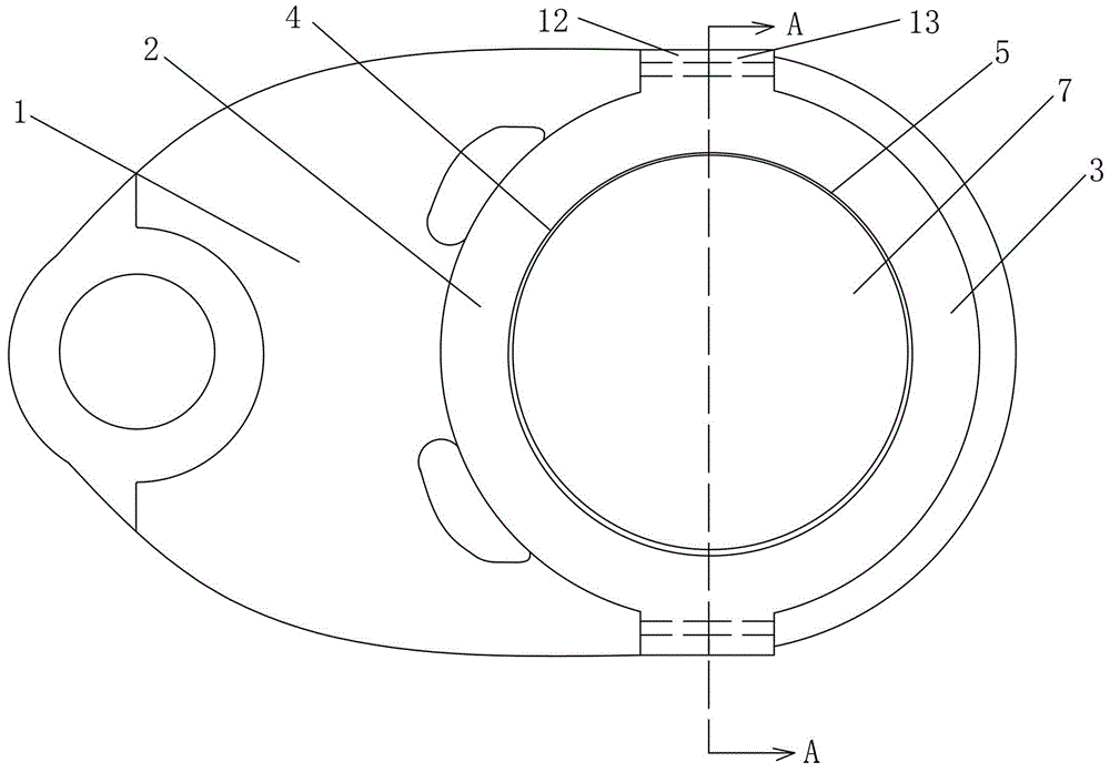
[0032] Such as Figure 2 to Figure 5 As shown, this embodiment provides a crankshaft connecting rod cover assembly for a cold heading machine, the body 1 includes a detachably connected connecting rod left cover 2 and a connecting rod right cover 3, and a connecting rod left cover 2 is provided. There is a semi-cylindrical first semi-cylindrical groove 4 and the first ear side 12 positioned at the top and bottom of the connecting rod left cover 2, and a semi-cylindrical second semi-cylindrical groove 5 and a semi-cylindrical second semi-cylindrical groove 5 positioned at the right side of the connecting rod are arranged on the connecting rod right cover 3. The second ear side 13 on the top and bottom of the cover 3, the first ear side 12 and the second ear side 13 are matched by fasteners, and the connecting rod installation through hole 6 is formed by the first semi-cylindrical groove 4 and the second semi-cylindrical groove 4. The structure formed after the groove 5 is synth...

Embodiment 3

[0036] Such as Figure 6As shown, the general structure of the crankshaft connecting rod cover assembly of a cold heading machine provided by this embodiment is the same as that of Embodiment 2, the difference is that, in order to facilitate processing, the oil groove 8 is formed by a longitudinal groove 14 and a longitudinal groove 14, more than one horizontal groove 15 is distributed at intervals for cross distribution, and the intersections of the vertical groove 14 and the horizontal groove 15 are connected to each other. Through such an oil groove, the distribution of the oil groove 8 is more uniform than that of a fishnet, and the heat dissipation effect is improved.


PUM


Abstract

The invention discloses a crankshaft connecting rod cap assembly of a cold header and a mounting method thereof. The crankshaft connecting rod cap assembly comprises a body, a connecting rod mounting through hole is formed in the body, two or more copper sleeves are distributed at the two ends of the connecting rod mounting through hole in the axial direction at intervals, and an oil groove is formed in the inner wall of each copper sleeve. According to the crankshaft connecting rod cap assembly of the cold header and the mounting method thereof, the multiple copper sleeves are arranged and axially connected to a crankshaft connecting rod in a sleeving mode at internals, so that the heat dissipation effect of the crankshaft connecting rod is not affected under the fact that the outer wall of the connecting rod is entirely wrapped with the copper sleeves, and meanwhile part of lubricating oil in the copper sleeves are taken out and stored under the effect of the crankshaft connecting rod; and then the part of lubricating oil is utilized to rapidly cool the copper sleeves and the crankshaft connecting rod, finally the heat dissipation effect is improved, and meanwhile the problem that the friction force is increased after using of a long time can be solved.

Description

technical field [0001] The invention relates to a crankshaft accessory of a cold heading machine, in particular to a crankshaft connecting rod cover assembly of a cold heading machine and an installation method thereof. Background technique [0002] Cold heading machine is a special equipment for mass production of fasteners such as nuts and bolts based on piers. The crankshaft on the cold heading machine is one of the key components of the cold heading machine, and its working state often directly or indirectly affects the overall performance index of the cold heading machine. The main function of the crankshaft is to drive the sliding table mechanism to reciprocate left and right to complete the pier processing of the fasteners. The crankshaft is connected to the driver through the connecting rod, and then drives the connecting rod to reciprocate through the driver, thereby driving the crankshaft to reciprocate. In order to effectively limit the position of the connecting...

Claims


Application Information

Patent Timeline
IPC IPC(8): F16C9/00F16N1/00
CPCF16C9/00F16N1/00F16C2322/12
Inventor 刘永华
Owner SIJIN INTELLIGENT FORMING EQUIP CO LTD
Why Eureka
Try Eureka