Automatic closing device and reaction device

An automatic sealing and reaction tank technology, which is applied in the direction of valve devices, engine components, functional valve types, etc., can solve the problems of inconvenient use and maintenance, narrowing the diameter of the air supply pipe, and the inability to seal tightly, so as to achieve good anti-backflow effect, Easy to manufacture and process, not easy to leak

Inactive Publication Date: 2017-12-26
虞瑞浩
View PDF0 Cites 4 Cited by
  • Summary
  • Abstract
  • Description
  • Claims
  • Application Information

AI Technical Summary

Problems solved by technology

The inventor found in the research that the anti-backflow device of the valve of the traditional air supply system has at least the following disadvantages during use: the use of check valves or one-way switches will seriously reduce the diameter of the air supply pipe, resulting in insufficient ventilation capacity, and It is easy to be damaged, causing a large amount of exhaust gas leakage; the use of check valves or one-way switches cannot be tightly closed, and a small amount of exhaust gas leakage will always occur under normal circumstances; the production is complicated, the use and maintenance are inconvenient, and the cost of use is high

Method used


Image

  • Automatic closing device and reaction device
  • Automatic closing device and reaction device
  • Automatic closing device and reaction device

Examples


Embodiment 1

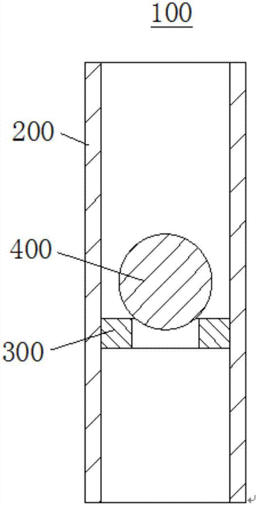
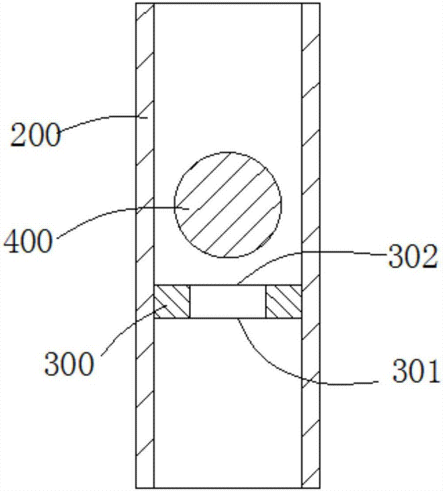
[0029] see Figure 1-2 ,in, figure 1 Shows a cross-sectional view of the air supply system in a non-working state, the non-working state refers to the state where no air is ventilated into the intake pipe 200, figure 2 It shows a cross-sectional view of the gas supply system in the working state. The working state is the state of pointing to the air in the intake pipe 200. The embodiment of the present invention provides an automatic sealing device, which is used to install in the reaction tank to prevent the reaction tank from being closed during the reaction process. The exhaust gas inside overflows from the air supply system, polluting the environment, which includes the air supply system.

[0030] The air supply system includes an air intake pipe 200 , an anti-backflow sealing ring 300 and an anti-backflow limiting member 400 .

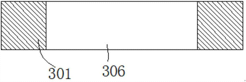
[0031] see image 3 , the anti-backflow sealing ring 300 is installed in the intake pipe 200, the anti-backflow sealing ring 300 is provided ...

Embodiment 2

[0040] see Figure 7-Figure 8 , this embodiment also provides an automatic closing device. This embodiment is a further improvement on the basis of the technical solution of Embodiment 1. The technical solution already described in Embodiment 1 is also applicable to this embodiment. In order to avoid repetition of description For cumbersomeness, the disclosed technical solution of Embodiment 1 will not be described in detail again.

[0041] Specifically, this embodiment is an improvement on the basis of Embodiment 1 that the anti-backflow limiter 400 will fall from the intake pipe 200 into the reaction tank. The air intake system 100 also includes a limiter, and the limiter is installed In the intake pipe 200, it is used to restrict the anti-backflow limiter 400 from sliding out of the intake pipe 200 in a direction away from the anti-backflow sealing ring 300. For example, when the intake system 100 is installed, the intake pipe 200 can only be vertical in one direction Sett...


PUM


Abstract

The invention discloses an automatic closing device and a reaction device. The closing device includes an air intake system. The air intake system includes an air intake pipe, an anti-backflow sealing ring and an anti-backflow limiting member. The anti-backflow sealing ring is installed in the lumen of the air intake pipe. , the anti-backflow sealing ring has an air inlet, the two ends of the inlet pipe are connected through the air inlet, the anti-backflow limiter is located in the inlet pipe, and the anti-backflow limiter has a working position and a non-working position, wherein the working position is The anti-backflow limiter closes the air inlet, and the non-working position refers to the space between the anti-backflow limiter and the anti-backflow sealing ring. The reaction device includes the automatic closing device. The structure of the automatic sealing device is simple and reasonable, convenient for manufacturing and processing, and the processing cost is low. At the same time, the anti-backflow effect of exhaust gas is good, the exhaust gas is not easy to leak, the entire automatic sealing device is not easy to be damaged, and has a long service life.

Description

technical field [0001] The invention relates to the field of chemical equipment, in particular to an automatic sealing device and a reaction device. Background technique [0002] At present, in the existing chemical production process, it is necessary to blow gas into the reaction equipment for reaction. When the reaction equipment is in a rolling and rotating dynamic state or in a static state, through the design of the reverse air supply system and the wind speed control, the air is blasted from the tail to supply air to the materials in the reaction equipment intermittently. , the air pressure in the main reaction equipment increases. When the blower stops supplying air, because the air pressure in the main reaction equipment is higher than the atmospheric pressure, the waste gas in the main reaction equipment will flow back along the air supply system, resulting in waste gas leakage and polluting the air environment. The prior art adopts a simple check valve or a one-wa...

Claims


Application Information

Patent Timeline
Patent Type & Authority Applications(China)
IPC IPC(8): F16K15/04F16K27/02B01J19/00
CPCF16K15/04B01J19/0053F16K15/044F16K15/048F16K27/0245
Inventor 虞瑞浩
Owner 虞瑞浩
Why Eureka
Try Eureka