
Workpiece clamping device of numerical control milling machine

A technology of CNC milling machine and clamping device, which is applied in positioning devices, metal processing mechanical parts, clamping and other directions, can solve the problems of irregular workpiece fixation, inability to meet the needs of users, and the clamping device is not firmly clamped. , to achieve the effect of increasing the scope of application

Pending Publication Date: 2017-12-26
JINGYIHENGZHUN TIANJIN CNC EQUIP CO LTD
View PDF5 Cites 8 Cited by
  • Summary
  • Abstract
  • Description
  • Claims
  • Application Information

AI Technical Summary

Problems solved by technology

[0003] Most of the existing clamping devices for CNC milling machine workpieces are simple in structure. After the workpiece is fixed, the clamping device does not clamp firmly during processing, causing the workpiece to shake, affecting the processing of the workpiece, and causing deviations in the processing of the workpiece. The clamping device cannot fix irregular workpieces well and cannot meet the needs of users. Therefore, we have designed a workpiece clamping device for CNC milling machines to solve the above problems

Method used


Image

  • Workpiece clamping device of numerical control milling machine
  • Workpiece clamping device of numerical control milling machine
  • Workpiece clamping device of numerical control milling machine

Examples


Embodiment Construction

[0014] The following will clearly and completely describe the technical solutions in the embodiments of the present invention with reference to the accompanying drawings in the embodiments of the present invention. Obviously, the described embodiments are only some, not all, embodiments of the present invention.

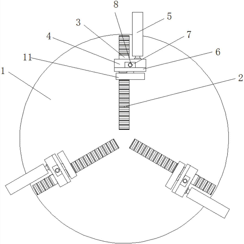
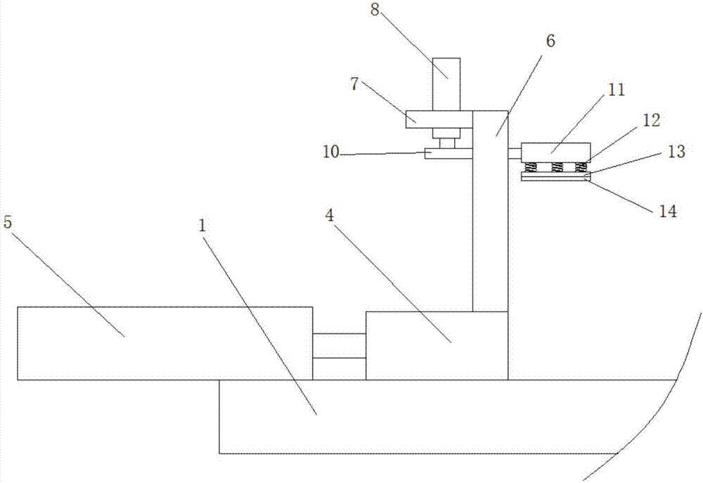
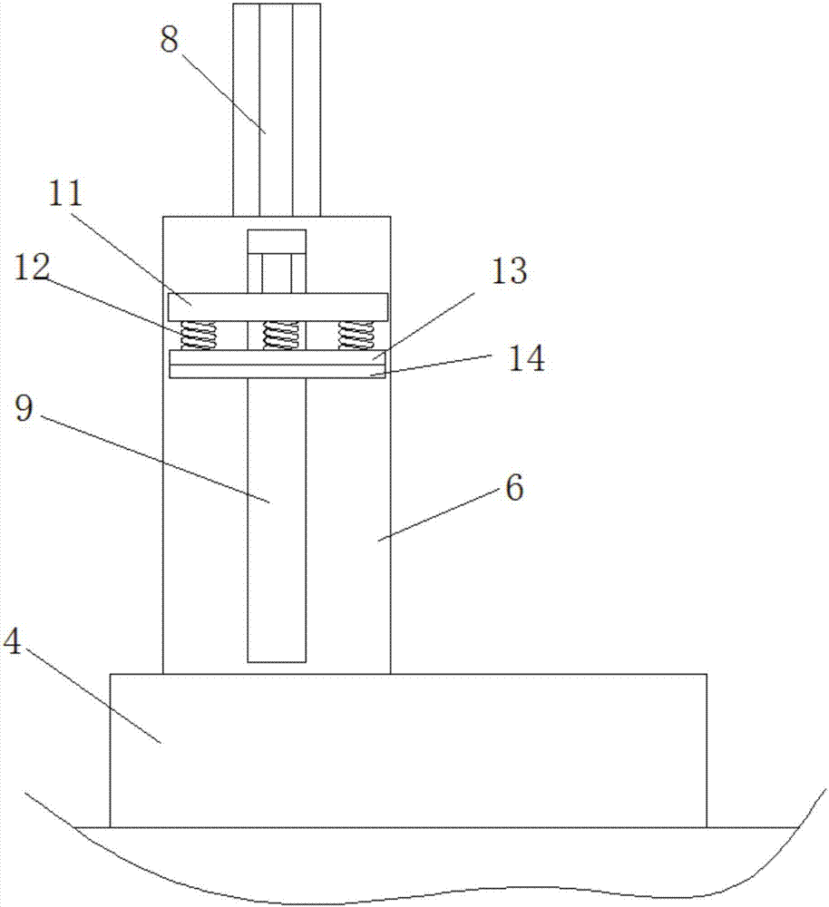
[0015] refer to Figure 1-3 , a workpiece clamping device for a CNC milling machine, comprising a fixed disc 1, the fixed disc 1 is fixedly installed on the CNC milling machine, and one side of the fixed disc 1 is provided with three sets of sliding grooves 2 equidistant along its radial direction, and the sliding grooves 2 are movable The sliding block 3 is installed, and the sliding block 3 is fixedly connected with the first clamping plate 4, the first clamping plate 4 is arranged close to the surface of the fixed plate 1, and the fixed plate 1 on one side of the sliding groove 2 is fixed along the length direction of the sliding groove 2 A first clamping cylinder...


PUM


Abstract

The invention discloses a workpiece clamping device of a numerical control milling machine. The device comprises a fixed disc; the fixed disc is fixedly mounted on the numerical control milling machine; three sets of chutes are formed in one side of the fixed disc in the radius direction at equal intervals; slide blocks are movably mounted in the chutes, and are fixedly connected with first clamping plates; the first clamping plates are tightly bonded on the surface of the fixed disc; first clamping cylinders are fixedly mounted on the fixed disc on one sides of the chutes in the length directions of the chutes; and piston rods of the first clamping cylinders are arranged towards the circle center of the fixed disc. Three sets of clamping mechanisms are arranged on the fixed disc; the clamping mechanisms can move in the chutes for adjustment; workpieces can be stably clamped through the clamping support force in three directions, and cannot be shaken even if in the machining process; and the positions of the three sets of clamping mechanisms can be adjusted to satisfy clamping of irregular workpieces so as to widen the application range of the device.

Description

technical field [0001] The invention relates to the technical field of numerically controlled milling machines, in particular to a workpiece clamping device for numerically controlled milling machines. Background technique [0002] CNC milling machine is an automatic processing equipment developed on the basis of general milling machine. The processing technology of the two is basically the same, and the structure is somewhat similar. CNC milling machines are divided into two categories without tool magazine and with tool magazine. Among them, the CNC milling machine with tool magazine is also called machining center. CNC machine tools are mainly used to process parts with complex shapes, but the structure of the fixtures used is often not complicated. The selection of fixtures for CNC milling machines can first be determined according to the batch of production parts. For single-piece, small-batch, and heavy-duty mold processing, positioning and clamping can generally be...

Claims


Application Information

Patent Timeline
Patent Type & Authority Applications(China)
IPC IPC(8): B23Q3/08B23Q3/06
CPCB23Q3/062B23Q3/08
Inventor 王振飞
Owner JINGYIHENGZHUN TIANJIN CNC EQUIP CO LTD
Learn More