
High and medium pressure joint heat supply system based on energy level matching

A technology of combined heating and energy level matching, which is applied in the direction of steam central heating system, heating system, household heating, etc., can solve the problems of energy level mismatch, weak correlation, and inability to meet process requirements at the same time, and achieve The effect of improving efficiency, improving reliability, and improving energy efficiency

Active Publication Date: 2017-12-22
GUODIAN NANJING ELECTRIC POWER TEST RES CO LTD +1
View PDF9 Cites 1 Cited by
  • Summary
  • Abstract
  • Description
  • Claims
  • Application Information

AI Technical Summary

Problems solved by technology

[0003] In the process of heating transformation of pure condensing units, since the flow design and manufacture of the unit have been formed, the expansion line of steam work has also been determined. Therefore, the extraction pressure and temperature of each extraction point are a set of relevant parameters; while industrial heating Depending on the production process, the required temperature and pressure are discrete, and the correlation is weak; therefore, the pressure and temperature of the steam extraction point of the unit cannot meet the steam quality required by the process at the same time. In order to meet the needs of heat users, pressure or The steam extraction point with a higher temperature grade extracts steam, and then reduces the temperature and depressurizes it for heating users, which results in a waste of energy levels that do not match

Method used


Image

  • High and medium pressure joint heat supply system based on energy level matching
  • High and medium pressure joint heat supply system based on energy level matching
  • High and medium pressure joint heat supply system based on energy level matching

Examples


Embodiment Construction

[0036] The substantive content of the present invention will be described in detail below in conjunction with the embodiments, but the protection scope of the present invention is not limited thereto. The experimental operations not described in detail in the experiment are routine experimental operations well known to those skilled in the art.

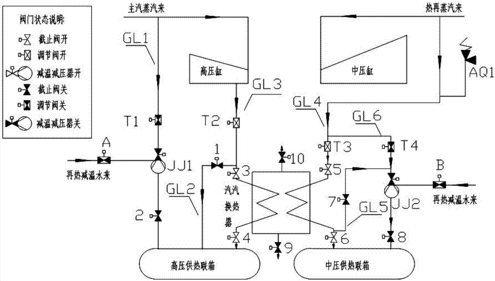
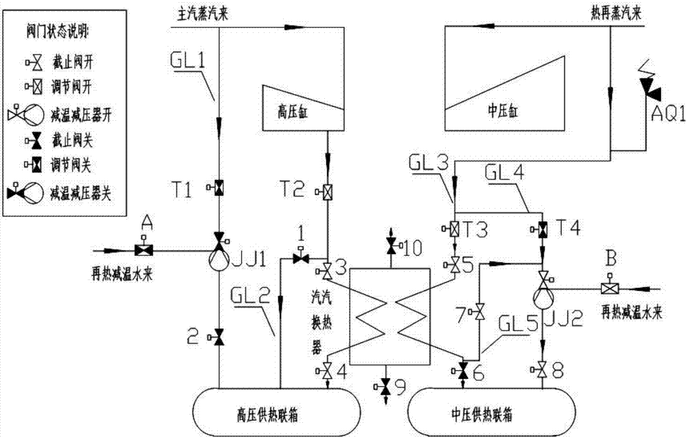
[0037] Such as Figure 1-3 A high- and medium-pressure combined heating system based on energy level matching is shown, including a high-pressure heating steam system, a medium-pressure heating steam system and a steam-steam heat exchanger system;

[0038] The high-pressure heating steam system includes: high-pressure heating pipeline (GL3), high-pressure heating extraction steam regulating valve (T2), high-pressure heating steam-steam heat exchanger inlet stop valve (3), high-pressure heating steam-steam heat exchanger Outlet cut-off valve (4), high-pressure heating steam-steam heat exchange bypass (GL2), high-pressure heating steam...


PUM


Abstract

The invention discloses a high and medium pressure joint heat supply system based on energy level matching. The high and medium pressure joint heat supply system based on energy level matching comprises a high pressure heat supply steam system, a medium pressure heat supply steam system and a steam-steam heat exchanger system. Firstly, the novel steam-steam heat exchanger system is designed, by means of the system, energy redistribution is achieved, temperature lowering of the medium pressure heat supply steam system is achieved, heating of high pressure heat supply steam is also achieved, and gradient utilization of energy is achieved by achieving two benefits; secondly, according to the heat supply scheme, steam extraction is used for replacing raw main steam heat supply, separate production of heat and power of the original high pressure heat supply steam is changed into combined production of heat and power, and the energy utilizing efficiency is improved; and thirdly, a high pressure heat supply bypass and a medium pressure heat supply bypass system are designed, and by means of cooperation of a heat supply main way and the bypasses, the variable work condition requirement of heat supply is flexibly and conveniently met. Thus, by means of the high and medium pressure joint heat supply system based on energy level matching, the energy utilizing efficiency is improved, and the heat supply reliability is also improved.

Description

technical field [0001] The invention relates to the field of heat supply, in particular to a large-scale thermal power unit simultaneously providing high-voltage and medium-voltage heat supply systems, and proposes a system for combined high-voltage and medium-voltage heat supply. Background technique [0002] Due to the needs of industrial production, in addition to the increase in the demand for electrical loads, some enterprises also have an increasing demand for heat loads. The heat supply demand is different according to the process requirements. There are high-pressure, medium-pressure and low-pressure heat supplies. ~400°C, steam is generally extracted from the primary extraction, cold re-stage or hot re-stage of the power plant; low-pressure heating: 0.3-0.6MPa, below 350°C, generally steam is extracted from the medium-low pressure connecting pipe of the power plant. [0003] In the process of heating transformation of pure condensing units, since the flow design an...

Claims


Application Information

Patent Timeline
Patent Type & Authority Applications(China)
IPC IPC(8): F24D1/08F01K17/02
CPCF01K17/02F24D1/08Y02E20/14
Inventor 谭锐殷戈蔡培涂朝阳钟健康张志业柯展煌严晓生杜清华
Owner GUODIAN NANJING ELECTRIC POWER TEST RES CO LTD
Learn More