
Strong-effect filtering type centrifugal fan

A centrifugal fan and filtering technology, which is applied in the field of powerful filtering centrifugal fan, can solve the problems of environmental pollution, inability to filter the air twice, and failure to meet the use requirements of range hoods, etc., and achieve good filtering effect and stable overall performance

Pending Publication Date: 2017-12-22
HANGZHOU DE&E ELECTRICAL CO LTD
View PDF0 Cites 8 Cited by
  • Summary
  • Abstract
  • Description
  • Claims
  • Application Information

AI Technical Summary

Problems solved by technology

Although the range hood itself can filter out a large amount of oil fume, some of the oil fume will still be discharged outside. However, the current ordinary centrifugal fan itself does not have filtering performance, nor can it perform secondary filtration on the air. The oily fume is directly discharged outside, which is easy to cause environmental pollution, especially in the catering industry in the community, which has high requirements for kitchen fume exhaust. Ordinary centrifugal wind cannot be filtered twice and cannot meet the requirements of the range hood.

Method used


Image

  • Strong-effect filtering type centrifugal fan
  • Strong-effect filtering type centrifugal fan
  • Strong-effect filtering type centrifugal fan

Examples


Embodiment Construction

[0020] The present invention will be further described below in conjunction with accompanying drawing and specific embodiment:

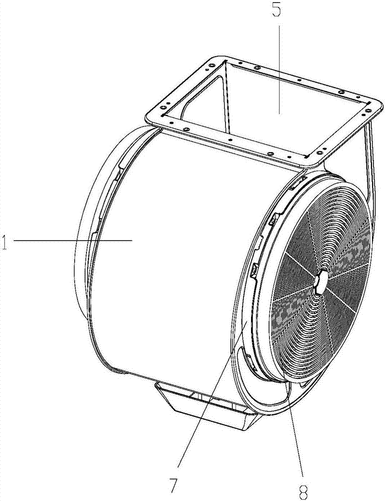
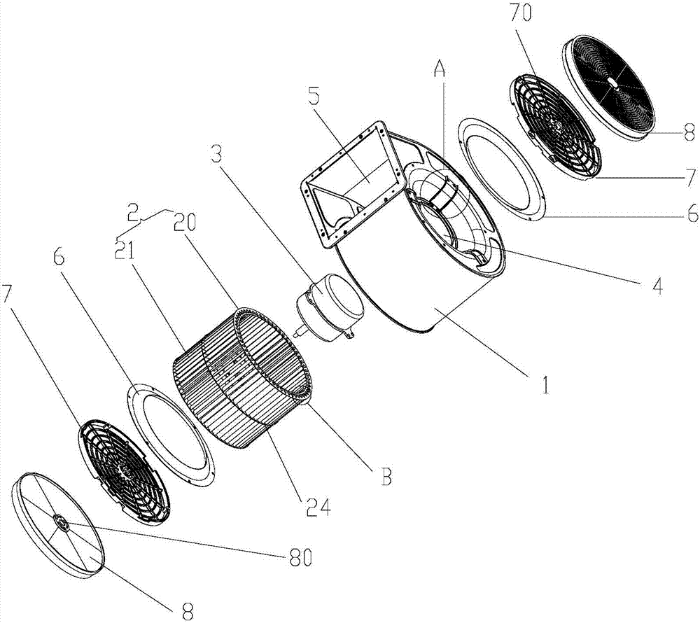
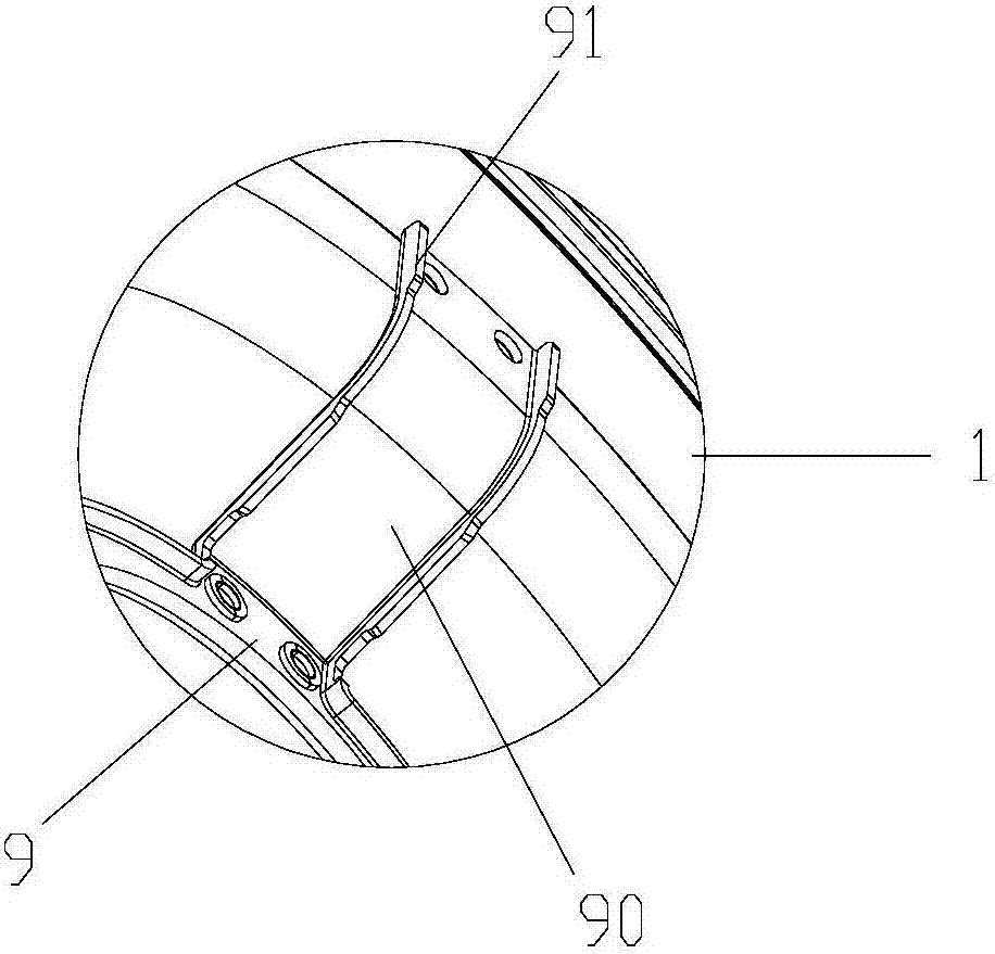
[0021] Such as figure 1 and figure 2 A powerful filtering centrifugal fan shown includes a volute 1, an impeller assembly 2 and a motor 3, the volute is provided with an air inlet chamber 4, an air duct 5 whose inner end communicates with the air inlet chamber, and the two impeller assemblies Each end is equipped with a wind guide cover 6, such as Figure 8 As shown, the air duct 5 is spirally distributed in the volute, the axial width of the air duct is equal everywhere, and the radial width of the air duct increases sequentially from the air inlet end to the air outlet end; image 3 As shown, the inner wall of the air inlet cavity is provided with a motor positioning ring 9, and three connecting bars 90 are arranged on both sides of the motor positioning ring, and the outer ends of the connecting bars are connected with the outer ends of the air...


PUM


Abstract

The invention relates to the technical field of fluid machinery, and discloses a strong-effect filtering type centrifugal fan. The strong-effect filtering type centrifugal fan comprises a volute, an impeller assembly and a motor, the volute is internally provided with an air inlet cavity and an air duct with the inner end communicated with the air inlet cavity, the two ends of the impeller assembly are provided with air guiding covers, a motor positioning ring is arranged on the inner wall of the air inlet cavity, a plurality of connecting strips are arranged on the two sides of the motor positioning ring, the outer ends of the connecting strips are connected with the outer end of the air inlet cavity of the volute through bolts, a connecting ring is arranged on the outer side of the motor, a plurality of connecting lugs are arranged on the connecting ring, and the connecting lugs are connected with the motor positioning ring through bolts; the two ends of the air inlet cavity are provided with activated carbon filtering assemblies, wherein the activated carbon filtering assemblies comprise inner isolation supports and outer isolation supports, the inner sides of the inner isolation supports and the inner sides of the outer isolation supports are provided with activated carbon cloth, and activated carbon particles are used for filling between the two layers of the activated carbon cloth. the device has the advantages that the tail gas of the range hood can be subjected to double filtration, the filtering effect is good, and the overall performance is stable. The strong-effect filtering type centrifugal fan has the beneficial effects that tail gas of a range hood can undergo double filtration, the filtering effect is good, and the overall performance is stable.

Description

technical field [0001] The invention relates to the technical field of fluid machinery, in particular to a powerful filtering centrifugal fan. Background technique [0002] Centrifugal fan is a machine that relies on input mechanical energy to increase gas pressure and discharge gas. It is a common fluid machine and is widely used in factories, mines, tunnels, cooling towers, building ventilation and other fields. At present, the smoke exhaust of the range hood also uses a centrifugal fan. The centrifugal fan has the characteristics of large exhaust air volume and low noise, and can quickly discharge the oil fume in the kitchen to the outside. Although the range hood itself can filter out a large amount of oil fume, some of the oil fume will still be discharged outside. However, the current ordinary centrifugal fan itself does not have filtering performance, nor can it perform secondary filtration of the air. The oily fume is directly discharged outside, which is easy to ca...

Claims


Application Information

Patent Timeline
IPC IPC(8): F04D25/08F04D17/08F04D29/70
CPCF04D17/08F04D25/08F04D29/703
Inventor 吕刚蔡无及孙利校
Owner HANGZHOU DE&E ELECTRICAL CO LTD
Learn More