Heat shrinkable pipe used in junction of multi-core fibers

A multi-core optical fiber and heat-shrinkable tube technology, which is applied in the coupling of optical waveguide, light guide, optics, etc., can solve the problems of residual air bubbles in the heat-shrinkable tube, twisted optical fibers, and occupying more racks, so as to achieve less rack space, The fiber is convenient and the effect of the fiber is convenient

Inactive Publication Date: 2017-12-19
成都兴兴蓉通信科技有限公司
View PDF0 Cites 0 Cited by
  • Summary
  • Abstract
  • Description
  • Claims
  • Application Information

AI Technical Summary

Problems solved by technology

[0005] The present invention solves the problems existing in the prior art that in projects where optical fiber splicing exists, construction personnel often connect multiple optical fibers through one optical fiber heat-shrinkable tube in order to save optical fiber splicing time. The inside of the tube will cause twisting between the optical fibers and residual air bubbles in the heat shrinkable tube during heat shrink protection, which is not conducive to later maintenance; at the same time, the fiber heat shrinkable tube only protects the single-core optical fiber, which is not conducive to the fiber coil and occupies more of the rack. To solve the problem, provide heat shrinkable tubes used in multi-core optical fiber splicing, which can connect multiple optical fibers in the same heat shrinkable tube at the same time, but the optical fiber and the pipeline are separated to avoid twisting between the optical fibers At the same time, the optical fiber is wrapped with a hot-melt tube alone to avoid the phenomenon that residual air bubbles in the heat-shrinkable tube affect the optical fiber transmission, and it is convenient for relevant personnel to carry out post-maintenance; at the same time, the fiber is more convenient to coil, occupying less racks, and can be more on the same tray. Fiber

Method used


Image

  • Heat shrinkable pipe used in junction of multi-core fibers

Examples


Embodiment

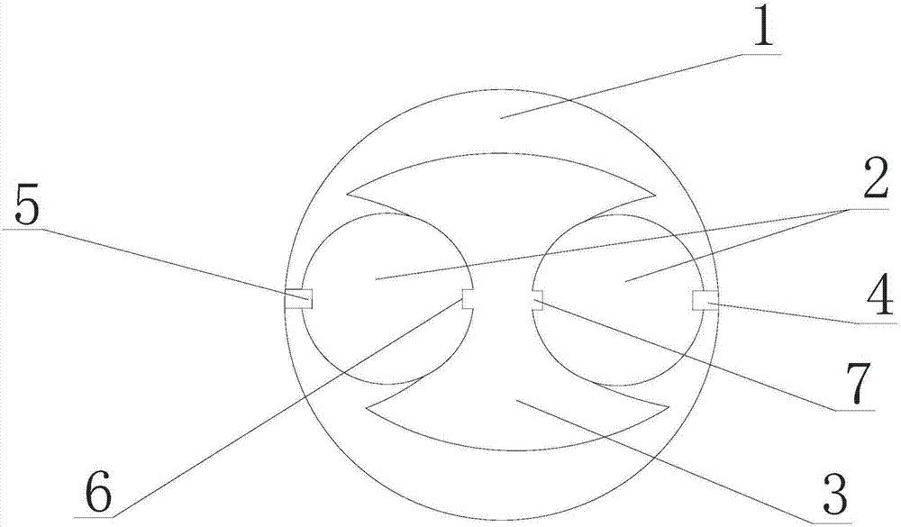
[0021] Such as figure 1 As shown, the heat-shrinkable tube used in multi-core optical fiber connection includes a heat-shrinkable tube 1, a heat-melt tube 2, a first strength member 3, and a second strength member 4. The number of the heat-melt pipes 2 is at least two, and the The melting tube 2 is arranged inside the heat-shrinkable tube 1, and the heat-melt tubes 2 are symmetrical along the central axis of the heat-shrinkable tube 1. The side of the thermal-melt tube 2 close to the heat-shrinkable tube 1 is provided with a groove 5, and the groove 5 is Square, arc-shaped or elliptical, the first reinforcement 3 is provided with a water chestnut 6 matching the groove 5, the first reinforcement 3 is placed in the groove 5 through the water chestnut 6 and connected with the heat-melt pipe 2, the groove 5 is along the A second groove 7 is provided on the symmetrical side of the central axis of the heat-melt tube 2, and the second groove 7 has the same shape as the groove 5, and ...


PUM


Abstract

The invention discloses a heat-shrinkable tube used in the connection of multi-core optical fibers, including a heat-shrinkable tube, a heat-melt tube, a first strengthening member, and a second strengthening member. Inside the tube, the heat-melt tubes are symmetrical along the central axis of the heat-shrinkable tube. The side of the heat-melt tube close to the heat-shrinkable tube is provided with a groove, and the first reinforcement is provided with a water chestnut matching the groove. Placed in the groove and connected with the heat-melt tube, the groove is provided with a second groove along the symmetrical side of the central axis of the heat-melt tube, and the second reinforcement is arranged between the heat-shrinkable tube and the heat-melt tube through the second groove. Improve the speed of optical fiber splicing; at the same time, it prevents construction workers from lazily connecting multiple optical fibers into a heat-melt tube at the same time, causing the optical fibers to twist each other and residual bubbles in the heat-shrinkable tube, which affects the transmission of the optical fiber and does not It is conducive to the later maintenance work; it is convenient for fiber coiling and reduces the occupation of the rack.

Description

technical field [0001] The invention relates to an optical fiber heat-shrinkable tube, in particular to a heat-shrinkable tube used in multi-core optical fiber splicing. Background technique [0002] Optical fiber heat-shrinkable tube refers to the single-core optical fiber heat-shrinkable protective sleeve. The single-core optical fiber heat-shrinkable protective tube is mainly used for the bare fiber part of the single-core optical fiber connection. Clear heat shrink tubing. The reinforcement is generally a stainless steel handle, a quartz handle or a ceramic handle. Optical fiber is an important part of the optical communication system, which provides a channel for optical signal transmission. An optical fiber usually consists of a core, cladding and coating. Both the core and the cladding are high-purity silica. Because the dopant doping ratio is different, the refractive index of the core is higher than that of the cladding, and the loss is lower than that of the cla...

Claims


Application Information

Patent Timeline
Patent Type & Authority Applications(China)
IPC IPC(8): G02B6/255
CPCG02B6/2558
Inventor 胡金雷
Owner 成都兴兴蓉通信科技有限公司
Why Eureka
Try Eureka