Vibration reducing device used for machining of annular thin-wall part
A technology for thin-walled parts and vibration damping devices, which is used in metal processing equipment, metal processing mechanical parts, manufacturing tools, etc., can solve the problem that the radial support force cannot cover the parts evenly, the stiffness and dynamic stability are poor, and the vibration damping effect is poor. problems, to shorten the production cycle, improve rigidity and dynamic stability, reduce the effect of machining vibration
- Summary
- Abstract
- Description
- Claims
- Application Information
AI Technical Summary
Problems solved by technology
Method used
Image
Examples
Embodiment 1
[0068] The damping device in this embodiment is used to process the combustion chamber casing of a certain type of engine. The material of the combustion chamber casing is a high-temperature nickel-based alloy, with a wall thickness of 3 mm to 6 mm, a height of 590 mm, and a diameter of For annular thin-walled parts, such as Figure 11 shown.
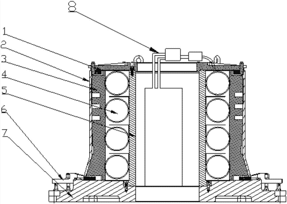
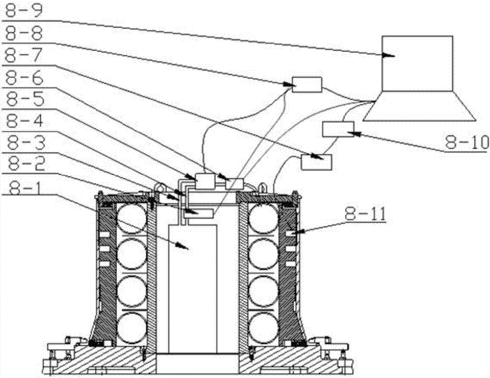
[0069] The damping device in this embodiment is as figure 1 , figure 2 , image 3 , Figure 4 As shown, it includes a base 7, twelve pressure plates 6 installed on the base for fixing the lower part of the processed annular thin-walled part, an axial limit assembly, a damping absorber 2, a gas damper and an intelligent pressure regulating system 8.
[0070] The axial limit assembly is composed of a pillar 5 and an upper cover plate 1. The pillar 5 is a cylindrical structure, and the lower end is provided with a flange connected to the base. The pillar is installed on the base through the flange and fixed with screws. The centerl...
Embodiment 2
[0087] The damping device in this embodiment is used to process the rear case of a high-pressure compressor of a certain type of engine. The material of the rear case of the high-pressure compressor is a high-temperature nickel-based alloy, the thinnest wall thickness is 2mm, the height is 274mm, and the diameter For annular thin-walled parts, such as Figure 15 shown.
[0088] The vibration damping device in this embodiment has the same overall structure as that in Embodiment 1, including twelve pressure plates 6 installed on the base for fixing the lower part of the processed annular thin-walled part, an axial limit assembly, and a damping absorber 2. Gas damper and intelligent pressure regulation system8. Difference with embodiment 1 is: (1) airbag 4 is two rubber annular airbags, and the airbag inflated gas is helium; (2) expansion block 3 is four nylon expansion blocks, and its shape and size are according to being Design of processing ring-shaped thin-walled parts; (3...
Embodiment 3
[0100] The damping device in this embodiment is used to process the front case of a high-pressure compressor of a certain type of engine. The rear case of the high-pressure compressor is a pair of open case, the material is TC2, the thinnest wall thickness is 1.9mm, the height is 530mm, and the diameter is 530mm. Such as Figure 19 shown.
[0101] The vibration damping device in this embodiment has the same overall structure as that in Embodiment 1, including twelve pressure plates 6 installed on the base for fixing the lower part of the processed annular thin-walled part, an axial limit assembly, and a damping absorber 2. Gas damper and intelligent pressure regulation system8. The difference from Example 1 is: (1) the gas inflated by the airbag 4 is nitrogen; (2) the shape and size of the inflatable block 3 are designed according to the processed annular thin-walled part; (3) the thickness of the damping absorbing part 2 is 20mm .
[0102] Using the damping device describ...
PUM
 Abstract
Description
Claims
Application Information
 - Generate Ideas
- Intellectual Property
- Life Sciences
- Materials
- Tech Scout
- Unparalleled Data Quality
- Higher Quality Content
- 60% Fewer Hallucinations
Browse by: Latest US Patents, China's latest patents, Technical Efficacy Thesaurus, Application Domain, Technology Topic, Popular Technical Reports.
© 2025 PatSnap. All rights reserved.Legal|Privacy policy|Modern Slavery Act Transparency Statement|Sitemap|About US| Contact US: help@patsnap.com


